 This project is a multi sensor telemetry system with Frequency Division Multiplexing (FDM).
This Telemetry System acquires several different sensor inputs, FM modulates each level by manipulating Direct Digital Synthesis increment values, transmits the resulting signal on a commercial FM radio band, and receives and decodes the original sensor levels.
Telemetry Transmitter System This project is a multi sensor telemetry system with Frequency Division Multiplexing (FDM).
Radio Wave Alarm This alarm circuit is sure to have the police beating a path to your door
This alarm circuit is sure to have the police beating a path to your door - however, it has the added advantage of alerting you to their presence even before their footsteps fall on the doormat.
 Suppose now that the circuit transmits at 1MHz. Suppose also that your radio is tuned to a frequency just below this. The 1MHz transmission will therefore not be heard by the radio. But bring a hand or a foot near to the sensor, and the transmitter's frequency will drop, and a beep will be heard from the radio.
Attach the antenna to a multiplug adapter that is plugged into the mains, and you will find that the Medium Wave transmission radiates from every wire in your house. Now place a suitably tuned Medium Wave radio near some wires or a plug point in your house, and an early-warning system is set up.
Instead of using the sheet of tin foil as the sensor, you could use a doorknob, or burglar bars. Or you could use a pushbutton and series resistor (wired in series with the 33K resistor - the pushbutton would short it out) to decrease the frequency of IC1a, so activating the system by means of a pushbutton switch. In this case, the radio would be tuned to a frequency just below that of the transmitter.
The circuit transmits on Medium Wave (this is the small problem with the police). IC1a, together with a sensor (try a 20cm x 20cm sheet of tin foil) oscillates at just over 1MHz. This is modulated by an audio frequency (a continuous beep) produced by IC1b. When a hand or a foot approaches the sensor, the frequency of the transmitter (IC1a) drops appreciably.
 Suppose now that the circuit transmits at 1MHz. Suppose also that your radio is tuned to a frequency just below this. The 1MHz transmission will therefore not be heard by the radio. But bring a hand or a foot near to the sensor, and the transmitter's frequency will drop, and a beep will be heard from the radio.
Attach the antenna to a multiplug adapter that is plugged into the mains, and you will find that the Medium Wave transmission radiates from every wire in your house. Now place a suitably tuned Medium Wave radio near some wires or a plug point in your house, and an early-warning system is set up.
Instead of using the sheet of tin foil as the sensor, you could use a doorknob, or burglar bars. Or you could use a pushbutton and series resistor (wired in series with the 33K resistor - the pushbutton would short it out) to decrease the frequency of IC1a, so activating the system by means of a pushbutton switch. In this case, the radio would be tuned to a frequency just below that of the transmitter.
ECC802S (12AU7 / ECC82) Tube SRPP Preamp Our friend Bruce has shared another one of his vacuum tube projects with the DIY community. His latest proj
Our friend Bruce has shared another one of his vacuum tube projects with the DIY community. His latest project is the ForeWatt Tube Preamplifier which is an ECC802S (12AU7 / ECC82) tube preamplifier. The tube preamp uses a SRPP topology with ECC802S tube that can be substituted with 12AU7 and ECC82 tubes. The gain of the preamp can be set 7 (~17dB) or 11 (~21 dB). The lower gain setting is realized when the cathode bypass capacitor is omitted. Naturally a switch can be used to change gain if desired. Shown in the photo below is the Type I preamplifier build which uses a manual rotary switch for input selection and a manual Alps Blue Velvet potentiometer to attenuate the input signal. The fabulous wooden enclosure was built by fellow hobbyist Jeff.

The power supply is solid state and the DC is used to heat the tubes. In the Type II version of the preamplifier shown in the photo below a remote control module is used for signal selection and signal attenuation. With the remote control module the preamplifier can also be used as a passive (no gain) preamplifier.

Bruce reports that with the ForeWatt preamplifier there is very clean with plenty of detail, a wide soundstage and that typical warm lush tube sound. The measure performance of the preamp is very good.
For full details about the ForeWatt Preamp, see the DIY ECC802S (12AU7 / ECC82) Tube SRPP Preamplifier project page.
Parallel Push-Pull 300B Tube Amplifiers Rudolf Moers from the Netherlands has kindly sent us details of his parallel push-pull 300B monoblock tube amp
Parallel Push-Pull 300B Tube Amplifiers
Rudolf Moers from the Netherlands has kindly sent us details of his parallel push-pull 300B monoblock tube amplifiers to share with the DIY Audio community. It should be quite obvious from the photographs that the design and construction of a pair of amplifiers this size is by no means a small undertaking. Rudolf tells us that he spent about 14 months designing and constructing the pair of monoblock amplifiers. The total cost of each amplifiers was about 1300 Euro, or about $1760US as of 29 September 2010. Each monoblock weighs 25 kg (55 pounds) and the overall dimensions are 530 mm deep, 390 mm high, 400 mm wide.

Schematics - Parallel Push-Pull 300B Tube Amplifier
The few notes on the schematics are written in Dutch. You can use a free online language translation service like Google Translate to translate them into English.
- Parallel push-pull 300B vacuum tube amplifier Schematic - [PDF - 270 kB]
- Parallel push-pull 300B vacuum tube amplifier Block Diagram - [PDF - 43 kB]
Parallel Push-Pull 300B Tube Amplifier
The input stages consists of a preamplifier and cathode phase splitter using a ECC82 (12AU7), amplitude amplification (driver) using a ECC99 and cathode followers using a ECC82 (12AU7) tube. The output stage uses four 300B directly heated power triodes in a parallel push-pull configuration (Ia = 40mA and Vak = 356 VDC) with no negative feedback. The output power for each monoblock is about 25W.
When powered on the heater supply for the ECC[82,99,82] tubes goes from 1.5 to 6.3 VDC in 30 seconds. Likewise, the 300B heater supply goes from 1.5 to 5.0 VDC in 30 seconds. Polarity of 5.0 VDC heater supply can be reversed with a switch. All the heater voltages are separated using galvanic isolation.
The high voltage supply uses a mercury filled full-wave rectifier AX50 and is switched on when all heater voltage are at about 90% of their final value. The AX50 rectifier limits the maximum output power to 25W.
The high voltage supply uses a mercury filled full-wave rectifier AX50 and is switched on when all heater voltage are at about 90% of their final value. The AX50 rectifier limits the maximum output power to 25W.

The enclosure is wooden and easily accessible with a hinged lid and there is plenty of interior space. The amplifier is constructed in a completely modular fashion with connectors. All the modules are built on prototyping boards.

Measurements Parallel Push-Pull 300B Tube Amplifier
Input power: 281 W(RMS) at 230V (50Hz/60Hz) mains voltage
Output power: 25 W(RMS) at 0 dB (775 mV) sine wave input signal
Efficiency: 8%
Bandwidth:
-0.1 dB at 20 Hz and 50 kHz at 25 W
-3.0 dB at 10 Hz and 100 kHz at 25 W
Distortion (THD) (distortion without hum suppression)
1.5% at 5 W and 10 Hz
4.0% at 23 W and 20 Hz
3.5% at 25 W and 50 Hz
3.5% at 25 W and 100 Hz
3.5% at 25 W and 200 Hz
3.4% at 25 W and 500 Hz
3.5% at 25 W and 1 kHz
3.5% at 25 W and 2 kHz
3.5% at 25 W and 5 kHz
3.5% at 25 W and 10 kHz
3.3% at 25 W and 20 kHz
2.7% at 25 W and 50 kHz
4.4% at 15 W and 100 kHz
THD < 1% at 2 W between 10 Hz and 20 kHz
THD < 2% at 10 W between 10 Hz and 20 kHz
THD < 3% at 15 W between 10 Hz and 20 kHz
Hum voltage over the loudspeaker is < -51 dB and inaudible with an ear against the loudspeaker.
Rudolf informs us that the design of this parallel push-pull 300B tube amplifier is explained in his new book "Fundamentele versterkertechniek met elektronenbuizen", ISBN 978-90-5381-226-6 which is currently only available in Dutch. However, an English translation "Fundamental Amplifier Techniques with Electron Tubes" is expected in November 2010. We will post an update when the English version is available.
UPDATE (2010-11-15) - the English translation Fundamental Amplifier Techniques with Electron Tubes is now available.
http://diyaudioprojects.blogspot.com/
Oatley K272A Head Amp audioXpress Review The December 2010 issue of audioXpress magazine includes a review of the $30AU Oatley Electronics K272A tube
Oatley K272A Head Amp audioXpress Review
The December 2010 issue of audioXpress magazine includes a review of the $30AU Oatley Electronics K272A tube based Headphone Amplifier Kit. Mark Houston completed a review of the Oatley Electronics K272 Headphone Amplifier Kit in August 2009 and since then many hobbyists have enjoyed this inexpensive audio kit. The hybrid headphone amplifier kit uses 6418 sub-miniature vacuum tubes and a headphone driver integrated circuit (PT2308). Adding appeal to the tube based kit is battery operation.

Highlights from the audioXpress Reliable Review of the Oatley Electronics K272A Headphone Amp by Aren van Waarde.
"Oatley Electronics (www.oatleyelectronics.com), which sells electronic parts and used equipment in New South Wales (Australia), has launched a small range of audio kits based on tube technology. My interest was raised by glowing reviews written by Mark Houston, ..."
"My initial impression of the sound of the K272A: warm, pleasant, and detailed. Organ music sounded great."
"... the K272A/Grado combination produced excellent sound: a fne bass (powerful and deep but not overblown), detailed mid-range, sweet top-end. Tonal colors of string instruments and vocals of male and female soloists were naturally represented. Many small, previously unnoticed details of recordings were revealed."
"In direct A/B comparisons, the K272A sounded better than the G4OEP (3/08 aX, p. 36) and even slightly better than the Stor class A amplifier (6/03 aX, p. 30)."
"For the asking price of 30 Australian dollars, the K272A is an absolute bargain. And it does not involve any dangerous voltages."
The full review of the Oatley Electronics K272A Headphone Amp is available as a direct download from audioXpress [PDF- 737kB].
Ultrasonic range finder using ATMega8515 This project is used to measure the distance using ultrasonic sensors. The ultrasonic signal passes through
This project is used to measure the distance using ultrasonic sensors. The ultrasonic signal passes through the atmosphere to a barrier, which we want to measure the distance. Part of this signal is reflected and travels back to the receiver. The time delay between sending and receiving signals are then determined by distance barriers.
The device was designed as a parking assistant for the car. It will help the driver while reversing the car to measure the amount of free space behind the vehicle. It is possible to download for this device are two types of software on the MCU. The first version is intended for parking assistant. After activating the measurement device measures the distance still to shutdown and it shows on the LCD. The second version is designed for manual distance measurement. After activating the device measures the distance and show it on LCD. For further measurements you need to activate it again with the switch.
Circuit Diagram

Operation
40Khz ultrasonic sensors are used. Microcontroller that controls the distance measurement is the Atmel AVR Mega8515. Measured distance is displayed on the display 2x16 characters. The device has two buttons. S2 button activates or deactivates a measurement button S1 is controlled backlight. The device also includes a connector for connecting the programmer SV1 via ISP.
When activated, the microcontroller will generate measurements using 8bit timer port B0 frequency 40kHz, which passes through inverters for amplifying the current and used to drive the ultrasonic transmitter that will broadcast the ultrasonic waves at 40khz. Simultaneously with the activation of the posting run 16bit timer that measures time by receiving the reflected signal. Sending a signal spread environment. After hitting the barrier is part of it is reflected and returns back to the sensor. The reflected signal is detected by the receiver, amplified in amplifier. Received signal is brought to an internal analog comparator of the microcontroller, in which income is due to rollover. At this point, the transmission is stopped, but mainly stops counting the time reception of reflected signals. 16bit timer is set so that the counting pulses 1?s. Measurement is treated in a way where there is no reception, there is a 16-bit counter overflows (after 65ms) and sending a timing stops. The display shows the inscription "out of reach". Further measurements are re-activated by pressing button S2. When receiving the reflected signal and the subsequent completion of counting time is 1?s counted the number of samples stored in the variable register, and timer is reset. Variable that contains the number of time samples must be multiplied with a constant length in order to display the measured distance.
When multiplied by the number of variables and sample length of time brings up a constant distance to the obstacle in centimeters. The result is rounded to one decimal place. The circuit also uses an LED. It starts flashing at a distance of less than obstacles to 50cm.
Before the first (after production equipment) measurement it is needed to set the reference voltage for comparator. This is done by the variable resistance R5. We will link connector JP2. By the meter set adjustment mode. The transmitter will continue to broadcast. Reference voltage to set the size to analog comparator to the maximum measured distance. Flip LED signals. When sufficient income reflected signal to flip and LED lights up. If one sensor , the LED should extinguish. Open the JP2 connector and the sensor is ready for measurement. Resistance trimmer R2 is used to adjust the contrast of characters on the LCD.
The disadvantage of this simple rangefinder is the speed of ultrasonic sound varies in air due to temperature change.
The speed of sound in air at different temperatures
| Temperature | Speed |
| -20°C | 319,3 m/s |
| 0°C | 331,6 m/s |
| 5°C | 334,5 m/s |
| 10°C | 337,5 m/s |
| 15°C | 340,6 m/s |
| 20°C | 343,8 m/s |
| 25°C | 346,3 m/s |
| 40°C | 355,3 m/s |
| 60°C | 366,5 m/s |
| 80°C | 377,5 m/s |
The rangefinder has a length constant calculated for a temperature of 25°C. For more accurate measurements it sis necessary to add a thermometer. So before each measurement, first measure air temperature, and choose the appropriate length constant. The speed will also get changed with variable pressure. This change is not as great as in the case of temperature change.
Download
Intelligent Train Engines We know that the railway network of India is the biggest in south Asia and perhaps the most complicated in all over the worl
The idea is whenever any engine observes a red signal on its track it will start decreasing its speed gradually and stops automatically at some distance from the signal pole. After then when it gets green signal the driver can manually start the train and go on. In the mean time when train has not stopped yet and a red signal becomes green then it crosses the signal pole with low speed and then driver can slowly increase the speed.
So now before the driver observes the red signal the engine itself observes it and automatically starts decreasing speed and then stops. The driver can feel relax in driving because he doesn’t have to take care about red signal. Even if he forgets to take any action on red signal then also we can avoid accidents by the implementation of this idea.
General description:
What we have to do is we have to attach a transmitter with signal pole which will start transmitting signals only when the red light is on. If there is green light no transmission. The engine has a receiver which catches these transmitted signals and takes desire actions.
Both the transmitter and receiver are of RF type with minimum range of 2 Km. so that train can get enough time to decrease its speed and stop before the signal pole with minimum swapping distance of 100-200 mt.
Here in our project we have used IR transmitter and receiver instead of RF for demo purpose. But same idea can be easily implemented with RF also with a little more cost.
Lets first discuss the demonstration model.
Demonstration Model:
The train engine runs on 24V DC motor so that we can easily vary its speed by varying applied voltage. The switching voltage is applied in step of 18 V, 15 V, 12 V and 9 V (min speed). The 230 VAC is step-down to 24 VAC by 12-0-12, 2 Ampere step down transformer. As shown in figure this 24 VAC line runs parallel with track at the top of the train. Movable tapping are taken from this line and fed to the internal circuit of engine. These tapping slides as the train runs on the track and give continuous supply to circuit. The IR sensor is placed at the top of the engine, senses the signals transmitted by IR transmitter attached to signal pole. Train track is straight and 20 ft long. Signal pole is placed at the end of track and train starts from farther end.

The project is divided in two parts 1) transmitter 2) receiver
The transmitter is housed in signal pole and it is activated only when red light is ON.
The receiver is housed in engine which senses the IR signals and takes suitable action.
Signal Pole IR Transmitter:-
The figure shows the schematic diagram of IR transmitter.

The heart of the circuit is IC555. The main component of the circuit is only IC555.
Connections:
Both ICs are connected in astable mode. The frequency of U2 is 0.5 Hz and U1 is 38 KHz. This is decided by RC components connected with it. The output of U2 is connected with reset pin (4) of U1. Thus the output of U2 controls the operation of U1 means it will switch on or off the output of U1. The output of U1 is fed to two IR LEDs through Darlington pair made up of Q1, Q2 and R5. The 9V DC battery is connected with circuit through SPDT switch SW1 as shown.
Operation:
As shown in figure when SW1 is in position as shown the transmitter is On and also the red LED is also ON. When switch changes its position the red LED and transmitter is off and only green LED will on. When the circuit is energized U2 will start generating high pulse at every 1 sec. as this pulse is fed to reset pin of U1 it will generate 38 KHz square wave and give it to IR leds. IR leds will generate IR beam of 38 KHz for the same time. Thus after every one second the IR beam of 38 KHz is generated for one second only. This cycle repeats till the red light is on.
Note: The range of this transmitter is limited to 10 ft only.
89C51 based IR receiver for Engine:
The IR receiver circuit housed in engine is as shown below.

The main components of the circuit are IR sensor TSOP 1738, microcontroller 89C51, current driver chip ULN2003A and all voltage regulator ICs (78XX series).
Intelligent Train Engines
Connections:
- 24 VAC is rectified by diode bridge D1 and filtered through C1 and given to all the regulated ICs as input.
- The output of 7805 is connected to 89C51 and TSOP and also to all the LEDs.
- Output of 7812 (last one) is connected to common coil terminal and to ULN
- The outputs of middle four regulated ICs are connected to DC motor through relay contacts.
- Output of TSOP is connected with pin P3.3 (INT1) of microcontroller
- All five leds are connected with port P0 as shown
- Input of ULN is connected with Port 1 pins P1.0-P1.3, and outputs are connected with second terminal of relay coil.
-
Operation:
- TSOP will detect the 38 KHz IR beam and gives the interrupt to 89C51.
- 89C51 will indicate the interrupt event on first (green) LED and energizes only one particular relay through ULN chip.
- When any of the four relay get energized the motor will get supply from it and it will start running
- As voltage is less it will run with less speed
- So now its the function of microcontroller to receive signal from IR sensor, decrease the speed of train gradually in four steps and then stop it. And this is done by software embedded in to 89C51.
How the project works?
- Initially when you switch on the supply 89C51 will switch all the relays RL1- RL4 one by one. So motor will get 9-12-15-18 V supply in steps and gradually increases its speed reaches max speed indicated by first red LED (P0.0).
- Now if the signal is green then train will cross the pole with same pole
- But if signal becomes red in between then IR sensor will detect IR beam and interrupts the 89C51
- Getting first interrupt 89C51 will switch off RL4 and switch on RL3 so now motor will get 15 V supply and its speed will be decreased. That’s indicated by second red LED (P0.1)
- Now 89C51 will wait for some time (2 to 3 sec) and train goes on with same speed. Again if still red signal is on 89C51 will be interrupted and this time it will switch on RL2. so now motor gets 12V supply and again its speed will be decreased indicated by third red LED (P0.2)
- The same procedure repeats if 89C51 is interrupted third times. Now motor runs at min speed (9 V) indicated by fourth red LED (P0.3)
- After same delay on receiving fourth interrupt all the relays will be switched off and motor is now stop so the train is also stopped. This is indicated by green LED.
- After this interrupts will be disabled. So now when red signal becomes green driver must reset the controller to start the train again.
The complete pseudo code with necessary comments is as given
org 00h
mov r0,#01h ; initialize the counter to count no. of interrupts
sjmp over ; jump above the interrupt subroutine
org 0013h ; interrupt 1 subroutine location
mov ie,#00h ; disable interrupt first
clr p0.0 ; interrupt indication on green led
inc r0 ; increment counter
acall delay ; call 0.1 sec delay
setb p0.0 ; reset green led
cjne r0,#02h,nxt2 ;if counter is 2 then decrease speed be one step (15 V)
mov p0,#0fbh
mov p1,#04h ; give indication on second red led
sjmp out
nxt2: cjne r0,#03h,nxt3 ; if counter is 3 then decrease speed be two step (12 V)
mov p0,#0f7h
mov p1,#02h ; give indication on third red led
sjmp out
nxt3: cjne r0,#04h,nxt4 ; if counter is 4 then decrease speed be three step (9 V)
mov p0,#0efh
mov p1,#01h ; give indication on fourth red led
sjmp out
nxt4: cjne r0,#05h,out ; if counter is 5 then stop the train
mov p0,#0feh
mov p1,#00h ; indicate it by green led.
out: acall dely ; call 2 sec delay every time when speed is changed
mov ie,#84h ; enable interrupt again
reti ; return from interrupt
over:mov p1,#01h ; main program starts from here starts train with min speed
acall dely ; and gradually increase it to max in four step
mov p1,#02h ; with 2 sec delay in between
acall dely
mov p1,#04h
acall dely
mov p1,#08h
mov p0,#0fdh
mov ie,#84h ; enable the interrupt
here: sjmp here ; continue loop
delay:
mov r6,#64h ; 0.1 sec delay
lop2:mov r5,#0FAh
lop1:nop
nop
djnz r5,lop1
djnz r6,lop2
ret
dely:
mov r7,#15h ; 2 sec delay
lop5:mov r6,#64h
lop4:mov r5,#0FAh
lop3:nop
nop
djnz r5,lop3
djnz r6,lop4
djnz r7,lop5
ret
end
DIY: A 3-Digit Digital Voltmeter (Atmega8) Here's a simple digital voltmeter based on Atmega8 microcontroller. It uses the in-built A/D converter to m
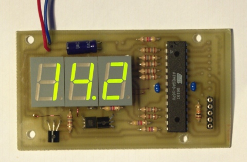
Source: http://tuxgraphics.org/electronics/200706/mini-digital-voltmeter.shtml
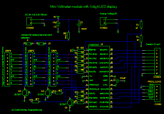
This same basic circuit can also be used to make a timer, counter, and a digital thermometer with some changes in the i/p side. Read rest of the project.
4093 CMOS IC Radio Wave Alarm
This very simple alarm circuit is sure to have the police beating a path to your door - however, it has the added advantage of alerting you to their presence even before their footsteps fall on the doormat.

The alarm circuit transmits on MW (Medium Wave) (this is the small problem with the police). IC1a, together with a sensor (try a 20cm x 20cm sheet of tin foil) oscillates at just over 1MHz. This is modulated by an audio frequency (a continuous beep) produced by 4093 CMOS IC1b. When a hand or a foot approaches the sensor, the frequency of the transmitter (CMOS IC1a) drops appreciably.
Suppose now that the alarm circuit transmits at 1MHz. Suppose also that your radio is tuned to a frequency just below this. The 1MHz transmission will therefore not be heard by the radio. But bring a hand or a foot near to the sensor, and the transmitter's frequency will drop, and a beep will be heard from the radio.
More for RF Alarm
Countdown Timer using 555 Timer
Countdown Timer:-
In this Countdown Timer project, a 555 IC, a counter IC and a transistor switch to activate a relay either ON/OFF (mode selected by a jumper) as soon as the counting period is over. The circuit consists of an oscillator, a ripple and two switching transistors.
Oscillator:-
The 555 is configured in the standard astable oscillator circuit designed to give a square wave cycle at a period of around 1 cycle/sec. A potentiometer is included in the design so the period can be set to exactly 1 second by timing the LED flashes. A jumper connection is provided so the LED can be turned off. As soon as power is applied to the circuit counting begins. The output pulse from pin 3 of the 555 is fed to a the clock input pin 10 of the 14-stage binary ripple counter, the 4020 (or 14020.).
parts required:-

Circuitdiagram:-

Ripple Counter:-
The counter output wanted is set by a jumper. Ten counter outputs are available: 8/16/32/64/128/256/512/1024/4096 and 8192 counts. If the 555 is set to oscillate at exactly 1.0Hz by the on-board trimpot then the maximum timer interval which can be set is 8192 seconds (just over 2 hours.) At the end of the counting of the countdown timer period a pulse is output on the pin with the jumper on it. The 14020 ripple counter advances its count on each negative transistion of the clock pulse from the 555. So for each output cycle of low-high-low-high the count is advanced by two. It can be set to an zero state (all outputs low) by a logic high applied to pin 11.
In this circuit C3, R4 and D1 are arranged as a power-on reset. When power is applied to the circuit C3 is in a discharged state so pin 11 will be pulled high. C3 will quickly charge via R4 and the level at pin 11 falls thus enabling the counter. The 14020 then counts clock pulses until the selected counter output goes high. D1 provides a discharge path for C3 when the power is disconnected.
You can change the components values of R1 and C1 to set the 555 count frequency to more than 1.0 Hz. If you change the count to 10 seconds then a maximum timer delay of 81920 seconds, or 22.7 hours, can be obtained.
Transistors:-The output from the 4020 goes to a transistor switch arrangement. Two BC547 are connected so that either switching option for the relay is available. A jumper sets the option. The relay can turn ON when power and counting start then turn OFF after the count period, or it can do the opposite. The relay will turn ON after the end of the count period and stay on so long as power is supplied to the circuit. Note that the reset pin of the 555 is connected to the collector of Q1. This enables the 555 during the counting as the collector of Q1 is pulled low
In real this is how an IC looks like.. First IC that was ever created .. Introduction of IC Integrated Circuits are usually called ICs or chips.
In real this is how an IC looks like..
First IC that was ever created ..
Introduction of IC
Integrated Circuits are usually called ICs or chips. They are complex circuits which have been etched onto tiny chips of semiconductor (silicon). The chip is packaged in a plastic holder with pins spaced on a 0.1" (2.54mm) grid which will fit the holes on stripboard and breadboards. Very fine wires inside the package link the chip to the pins. 
The pins are numbered anti-clockwise around the IC (chip) starting near the notch or dot. The diagram shows the numbering for 8-pin and 14-pin ICs, but the principle is the same for all sizes.
Common ICs
Below, the most common ICs are shown. (Those parts that I use most.)
For extensive details on each part, see the corresponding data sheet.
The part numbers of the SN74 series ICs are written with a 74, often followed by LS or HC.
LS (Low power Shottky) indicates low power consumption. HC indicates the device is High speed C-MOS (Complementary-Metal Oxide Semiconductor), and is also a low power consumption IC.
The average current consumption for each type of chip is listed below.
The current shown is for when the device is in a LOW state output. In the case of the LOW state output, current consumption is much greater than in the HIGH state output.


| SN7400 | ----- | 22mA |
| SN74LS00 | ----- | 4.4mA |
| SN74HC00 | ----- | 0.02mA |
Several kinds of ICs are not available in the LS or HC type. For example, SN7445 is not available in LS or HC. It is available only as SN7445, the normal type.
| Name | Function | Vcc | Pin Assign(Top View) | Remarks |
|---|---|---|---|---|
| SN74HC00 | Quad 2 Input NAND | +5V |  | 2 input NAND circuits entered 4 pieces |
| SN74HC04 | Hex Inverters | +5V |  | Inverter circuit entered 6 pieces Details |
| SN74LS42 | BCD to DECIMAL Decoder | +5V |  | One of output takes LOW state serected by the binary input. |
| SN7445 | O.C. BDC to DECIMAL Decoder/Driver | +5V | | Open collector type of 7442 Max current of output is 80mA. |
| SN74LS47 | BCD to Segment Decoder/Driver | +5V |  |  Front View Front ViewDriving IC of ‚Vsegments LED. Open collector type Max resistance voltage:15V 6 and 9 disply type:  Related 74247 |
| SN74HC73 | Dual JK-FFs With Clear | +5V |  | 2 pieces of JK-FF |
| SN74LS90 | Decade Counter | +5V |  | Asynchronous 2 + 5 counter. Async preset : 9 Async clear Related 74290 74390 |
| SN74HC93 | 4-Bit Binary Counter | +5V |  | Asynchronous 2 + 8 counter. |
| SN74HC123 | Dual Retriggaerable Single Shot | +5V |  | Single shot resister holds the output in the required time from the input states goes to ON. The output holding time corresponds to C(capacitor) and R(resistor) connected to the Cext(External capacitor) and Rext(External resistor) respectivly. |
| SN74LS247 | BCD to Segment Decoder/Driver | +5V | | Front View 6 and 9 disply type:  Related 7447 |
| SN74LS290 | Decade Counter | +5V |  | This type is the same as the SN7490, with a different layout of pins. Related 7490 74390 |
| SN74HC390 | Dual Decade Counters | +5V |  | Type that inserted 2 SN7490. Presetting 9 is omitted . Related 7490 74290 |
| 4040B | 12Bit Binary Counter (CMOS) | +5V |  | 12-stage Binary counter. It has a clear function. Counts downward with an external clock pulse. |
| 4541B | Progarammable Oscillator/Timer (CMOS) | +5V |  | Programmable 16 stage binary counter. Used in RC oscillation circuits, power reset, output control circuits. Tap outputs of 8, 10, 13, 16 bits are possible by the control terminal. |
| NE555 | Timer | +4.5 to +16V |  | Max frequency: 500kHz Temperature drift: 0.005%/°C. Max output current: 200mA. Delay time setting :several micro sec to several hours |
| LM386N-1 | Low frequency electric power amplifier | +4 to 12V |  | Max output: 660mW Load: 8 to 32-ohm Waiting current: 4mA |
| LM386N-4 | Low frequency electric power amplifier | +5 to 18V | | Max output: 1.25W Load: 8 to 32-ohm Waiting current: 4mA |
| TA7368P | Low frequency electric power amplifier | +2 to +10V |  | Max output: 1.1W Load: 4 to 16-ohm |
| uPC319 | Voltage comparator | 5 to 18V ±5 to ±18V |  | Standard general use comparator with single power supply/dual power supply operation Other compatible ICs LM319 NJM319 AN1319 |
| 7975 | Multi-melody IC (CMOS) | +1.5 to +3V |  | Melody IC that includes 8 pre-programmed melodies. It has 2 sound resources and a settable envelope. Title |
Three Terminal Voltage Regulator
It is very easy to get stabilized voltage for ICs by using a three terminal voltage regulator.
The power supply voltage for a car is +12V - +14V. At this voltage, some ICs can not operate directly except for the car component ICs. In this case, a three terminal voltage regulator is necessary to get the required voltage.
The three terminal voltage regulator outputs stabilized voltage at a lower level than the higher input voltage. A voltage regulator cannot put out higher voltage than the input voltage. They are similar in appearance to a transistor.

On the left in the photograph is a 78L05. The size and form is similar to a 2SC1815 transistor.
The output voltage is +5V, and the maximum output current is about 100mA.
The maximum input voltage is +35V. (Differs by manufacturer.)
On the right is a 7805. The output voltage is +5V, and maximum output current is 500mA to 1A. (It depends on the heat sink used)
The maximum input voltage is also +35V.
There are many types with different output voltages.
5V, 6V, 7V, 8V, 9V, 10V, 12V, 15V, 18V
Component Lead of Three Terminal Voltage Regulator
Because the component leads differ between kinds of regulators,
you need to confirm the leads with a datasheet, etc.

Example of 78L05
Part number is printed on the flat face of the regulator, and indicates the front.
Right side : Input
Center : Ground
Left side : Output

Example of 7805
Part number is printed on the flat face of the regulator, and indicates the front.
Right side : Output
Center : Ground
Left side : Input
Opposite from 78L05.
Subscribe to:
Posts (Atom)