Description for simplest electronic code lock(1 resistor based) circuit

Tags
Description.

This is of course the simplest electronic code lock circuit one can make. The circuit uses one transistor, a relay and few passive components. The simplicity does not have any influence on the performance and this circuit works really fine.

The circuit is nothing but a simple transistor switch with a relay at its collector as load. Five switches (S0 to S4) arranged in series with the current limiting resistor R2 is connected across the base of the transistor and positive supply rail. Another five switches (S5 to S9) arranged in parallel is connected across the base of the transistor and ground. The transistor Q1 will be ON and relay will be activated only if all the switches S0 to S4 are ON and S5 to S9 are OFF. Arrange these switches in a shuffled manner on the panel and that it. The relay will be ON only if the switches S0 to S9 are either OFF or ON in the correct combination. The device to be controlled using the lock circuit can be connected through the relay terminals. Transformer T1, bridge D1, capacitor C1 forms the power supply section of the circuit. Diode D2 is a freewheeling diode. Resistor R1 ensures that the transistor Q1 is OFF when there is no connection between its base and positive supply rail.

Circuit diagram.


S: www.circuitstoday.com

LED lamp circuit that can be operated from the mains voltage

Tags

Circuit Diagram for LED Lamp


This circuit is designed by Mr Seetharaman Subramanian and we are very glad to publish it here. In this article he is showing a method to convert a broken/defunct CFL into a LED based power saving light.

The is just a LED lamp circuit that can be operated from the mains voltage. A string of five LED is driven using a capacitive transformer less power supply. In the circuit 0.47uF/400V Polyester capacitor C1 reduces the mains voltage. R1 is a bleeder resistor which drains the stored charge from C1 when the AC input is switched OFF. Resistors R2 and R3 limits the inrush of current when the circuit is switched ON. Diodes D1 to D4 forms a bridge rectifier that rectifies the reduced AC voltage and C2 acts as a filter capacitor. Finally Zener diode D1 provides regulation and the LEDs are driven.

Photos.

Seetharaman’s words about the circuit: I am sending you a table lamp made from defunct energy saver lamp with broken tubes. CFL converted into LED lamp. Most of the components will be available in ones scrap box. Few components available in the CFL PCB also can be used.

Procedure

1. Carefully remove the broken glasses

2. Open the assembly carefully

3. Remove electronics and discard

4. Assemble the circuit in dot matrix PC or on a 1mm laminate sheet.

5. Cut a round laminate sheet with (scissor)

6. Mark the position of the 6 round holes on the sheet

7. Drill the holes to suit the LEDs to flush fit in the six holes

8. Use a dab of adhesive to keep the LED assembly in position

9. Close the assembly

10. Ensure the internal wiring does not touch each other

11. Now test on 230Volt AC

Your nice compact table lamp / puja room lamp / passage lamp is ready for use.

S: www.circuitstoday.com

analysis for Norton theorems

Tags
Norton theorems is that, any two of the series can be converted into an equivalent set of which consists of a current source (IN) and a norton equivalent resistans (RN) with a source flow dipararel it.

Steps to find the rope it is:
1. Specify two of the series who want to search string norton.

2. Determine the amount of the cash flow it is that flows between two terminals in the series who want to search string norton. Because we want to explore the current two terminals must be linked to a series of short first so you can cash flow.

3. Specify the size of the resistans norton is the equivalent resistans review / calculated from the two-terminal series of string which you want to search it. Resistans determine at the time it is, all sources should be eliminated. Voltage source into a series of short relationships and sources of flow into a series of open relationship.

4. Picture a rope to its norton.

  • Example
Specify the Norton string it, for a series connected with resistor RL = 6Ω on the image below!
Teorema Norton

Answer:
To simplify, first series of pictures which you want to rope it is sought, such as the following picture
Teorema Norton

Determine the flow norton (IN):
relationship short of the first two series of the string it would look for it, so that the circuit is to be:
Teorema Norton
Resistans R2 will not flow because there is a short relationship. Cash will flow through the short series. Norto Flow (IN) then it is, to be:
Teorema Norton

RN specify:
first remove all sources that are in series, so that the voltage source into a series of short relationship (V= 0). Series is to be:
Teorema Norton
Then combine with the search results Rn and In, of norton String it, can picture the following:
Teorema Norton

How a voltage source in series with the new resistance can be transformed into a source of flow ?

Tags
When we apply a method to analyze a series of DC, may be necessary to change the source of flow into voltage source or voltage source into a source flow.


Not any source can be transformed. A voltage source in series with the new resistance can be transformed into a source of flow in parallel with resistance. Instead of a flow in parallel with the resistans transformation can be a source of voltage in series with the resistans. In general, how to change the power source into a source of other types shown in the picture below:
Transformasi Sumber

  • Example
with the Sources Transformation, Change voltage source in the image below into the source flows!
Transformasi Sumber

Answer:
Transformasi Sumber

The results shown in the picture below:
Transformasi Sumber

  • Example 2
with the Sources Transformation, Change flow Source on the images below are a source of tension!
Transformasi Sumber

Answer:
Transformasi Sumber

The results shown in the picture below:
Transformasi Sumber

Stages to implement a Nodal / Simpul / Titik Analysis

Analisis Nodal/Simpul/Titik Untuk mempermudah Analisa Rangkain Elektronika


Nodal / Simpul /titik Analysis By using this method, we will first obtain the size of the voltage on each of a series in which later can be used to explore the amount of electricity the other.

Stages to implement a Nodal / Simpul / Titik Analysis is this:
1. Determine the amount of twist in the series.
2. Choose a Simpul reference mark and the rest with a certain voltage, such as V1, V2, V3 and so on.
3. Determine the direction of flow on each knot. On a note that is not the directions, the directions are usually chosen exit / leave the simpul. Rename the current I1, i2, I3, and so on.
4. Apply Kirchoff current law at every twist in the simpul, except reference. Consider that all flows that do not know the directions, will leave every simpul.
5. Complete equality of linear simultan

Example
From the following series, specify the size of the voltage is in each simpul it!
Analisis Nodal/Simpul/Titik

Answer:
Determine the number of simpul:
Analisis Nodal/Simpul/Titik

Simpul V1:
Analisis Nodal/Simpul/Titik

Simpul V2:
Analisis Nodal/Simpul/Titik

Expressed in the form of a matrix:
Analisis Nodal/Simpul/Titik

electric current(I),Power(P) and Energy(E)equations explanation

Tags
  • Arus listrik|Electric current (I)
Electric current states that the number of load flow in a certain direction on a series of electrical elements of each unit of time. Mathematically expressed by:


with,
I: electric current (in ampere)
Q: electric load (in coulomb)
t: time (in seconds)
Than the electric current magnitude have also have a direction (the direction indicated by arrow), which describes the direction of moving cargo electricity.


Tegangan|Electric current (V)
Electric current Work is needed to move the load of 1 coulomb positive from one point to the tip of the point the other end. Mathematically expressed by:


with,
V: voltage (in volt)
Q: electric load (in coulomb)
W: electrical energy (in Joule)

Usually termed as the voltage potential difference between the two dots on a series of elements. For states marked with a voltage algebra plus-minus polarity (+,-) that point with the other point. As an illustration shown in the picture below:


A point means is 5 volt more positive than the point B or point A is -5 volt more negative than point B.

  • Daya|Power (P)
Power the rate of electrical energy per unit time to move a load of 1 coulomb through a series of elements. The energy absorbed is proportional to the number of cargo that moved every second (or flow) and comparable with the energy needed to move one coulomb through a series of elements (or tension). Mathematically expressed by:


From the above formula can be derived the power formula as follows:


Sign agreement to current, voltage, power, and concluded in the following picture


Image shows an edge if the element is V volt more positive towards the end of the other point, and if I enter a flow of elements through the end of the positive, then the power P = VI is absorbed by these elements and vice versa.

  • Energy (W)
Energy Is the result of the multiplication with the power of time. Mathematically expressed by:

Importance of Kirchoff law

Tags
Hukum Kirchoff Arus


States that "all the algebraic number of the flow enters a knot / point in the series is a zero" or "the amount of flow that enters the knot in a series with the same amount of flow that is out of the knot."
Expressed mathematically with
Hukum Kirchoff Arus

As an illustration shown in the picture below:
Hukum Kirchoff Arus

So based on the law applicable kirchof flow:
Hukum Kirchoff Arus


-Hukum Kirchoff Tegangan

States that "the amount of voltage that all algebraic corral a road closed (loop) in a series of electricity is zero." Mathematically expressed by:
Hukum Kirchoff Tegangan

As an illustration shown in the picture below:
Hukum Kirchoff Tegangan

So based on the law applicable kirchoff voltage:
Hukum Kirchoff Tegangan


-Example Kirchoff Tegangan

Determine the voltage of the unknown in the following series!
Hukum Kirchoff Tegangan

Answer:
By applying Kirchoff voltage law is
Hukum Kirchoff Tegangan

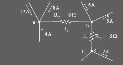
-Example Kirchoff Arus

Determine the flow of the unknown from the image below!
Hukum Kirchoff Arus

Answer:
By applying the law kirchoff flow on a point, it will be valid
Hukum Kirchoff Arus

By applying the law kirchoff flow at the point b, it will be valid
Hukum Kirchoff Arus

By applying the law kirchoff flow at the point c, it will be valid
Hukum Kirchoff Arus

LS7220 MOS digital lock circuit (Rangkaian Kunci Digital Ber-password)

Tags
LS7220 is a MOS digital lock circuit. When wired to a ten-digitkeypad, the circuit will recognize one four-digit combination out of a possible 5040 combinations. The LS7220 is configured with the features required for an Automotive Ignition Anti-Theft Digital Lock (See Figure 5). These
features include Sense input which enables the IC, Save Memor for Valet Parking, Convenience Delay to maintain Unlock condition for short term interruptions of the Sense input and Save Status and Lock Status outputs which can be used for direct drive of LED indicators.

following simple example the use of LS 7220 as Electronic Combination Lock

Rangkaian Kunci Digital  Ber-password
Skema Rangkaian Kunci Digital Ber-password


List komponen Electronic Combination Lock
  • C1 1uF/25Vr
  • C2 220uF/25V
  • R1 2.2K
  • Q1 2N3904 NPN Transistor 2N2222
  • D1 1N4148 Rectifier Diode
  • K1 12V SPDT Relay, Any appropriate relay with 12V coil
  • U1 LS7220 Digital Lock IC
  • S1-S12 PST Momentary Pushbutton
  • HD1 12 Position Header

Rangkaian Kunci Digital Ber-password is the circuit diagram of a simple electronic combination lock usingLS 7220. Rangkaian Kunci Digital Ber-password Password Digital can be used to activate a relay for controlling (on & off) any device when a preset combination of 4 digits are pressed.The circuit can be operated from 5V to 12V.

To set the combination connect the appropriate switches to pin 3,4,5 and 6 of the IC through the header.As an example if S1 is connected to pin 3, S2 to pin 4 , S3 to pin 5, S4 to pin 6 of the IC ,the combination will be 1234.This way we can create any 4 digit combinations.Then connect the rest of the switches to pin 2 of IC.This will cause the IC to reset if any invalid key is pressed , and entire key code has to be re entered.

When the correct key combination is pressed the out put ( relay) will be activated for a preset time determined by the capacitor C1.Here it is set to be 6S.Increase C1 to increase on time.

For the key pad, arrange switches in a 3X4 matrix on a PCB.Write the digits on the keys using a marker.Instead of using numbers I wrote some symbols!.The bad guys will be more confused by this.

flip-flop and its types

Tags
Flip-flop is Multivibrator families that have two or keadaaan called Bistobil stable Multivibrator. A series of flip-flop has sekuensial because of the nature of the system is set with the hours or credits, the systems are working in sync with the row balance berperiode T called the system clock (System Clock or truncated to CK).


function of a series of flip-flop that is the main memory (store information) 1 bit or a 1 bit storage cells. In addition, flip-flop can also be used on the set of Shift Register, Counter, and a series of others.


TYPE OF FLIP-FlOP
1. RS-FF (the bundle of NAND gate)


Truth table gerbang Logika RS-FF


2. RS - FF with Clock
With the Clock will make a working FF-RS synchronously or active sync

Truth table gerbang Logika RS-FF With Clock


3. FLIP-FLOP D
shortage that occurred in the RS Flip-flop is at the R = 1, S = 1 should be avoided (may not happen). One way to overcome this is to allow only an input only. FF-D is able to resolve the issue.


Truth table gerbang Logika FLIP-FLOP D


4. FLIP-FLOP JK
Implementation of the gate / JK-FF series and its logic symbol
the picture is as follows:


Truth table gerbang Logika FLIP-FLOP JK

Advertisement