integrated output amplifier used in motor vehicles and other battery operated applications


The integrated output amplifier described in this article consists of little more than one integrated circuit. It is intended especially for use in motor vehicles and other battery operated applications. Although it appears simple and hardly worth looking at, the amplifier can produce an appreciable audio power output.

technical data Properties High power output through Class-H operation
Low power dissipation during reproduction of music signals
Proof against short-circuits
Protection against excessive temperatures
Standby switch
No power-on or power-off clicks
Visible error indication
Measurement results (at Ub=14.4 V)
Supply voltage 8–18 V
Sensitivity 760 mV r.m.s.
Input impedance 70 kΩ
Power output 54 W r.m.s. into 4 Ω (f=1 kHz; THD+N=1%)
Harmonic distortion (THD+N) at 1 W into 4 Ω: 0.046% (1 kHz)
0.29% (20 kHz)
at 35 W into 4 Ω: 0.12% (1 kHz)
0.7% (20 kHz)
Signal-to-noise ratio (with 1 W into 4 Ω) 88 dBA
Power bandwidth 7.5 Hz – 185 kHz (at 25 W into 4 Ω)
Quiescent current about 135 mA (‘on’)

COMPONENTS LIST
Resistors:
R1 = 1MΩ
R2 = 4kΩ7
R3 = 1kΩ
R4 = 100kΩ
Capacitors:C1,C2 = 470nF
C3,C4 = 10μF 63V radial
C5,C6,C8 = 4700μF 25V radial
(18mm max. dia., raster 7.5 mm)
C7 = 100nF, raster 5 mm
Semiconductors:
D1 = high-efficiency-LED
IC1 = TDA1562Q (Philips)
Miscellaneous:
S1 = single-pole on/off switch
Four spade connectors, PCB mount
Heatsink for IC1 (Rth<2.5>

mj15003 transistors and amplifier 250-500w


GENERAL DISCRIPTION :The circuit is based around (TL 071) manufactured by NATIONAL semiconductors (MJ15003) by ON semiconductors It is a high fidelity audio power amplifier. Designed for demanding consumer and pro-audio applications. You can also use this circuit with AV receivers, Audiophile power amps, Pro Audio High voltage industrial applications etc Amplifier output power maybe scaled by changing the supply voltage and number of output devices.

General Specifications
Rated Power Output
(20Hz to 20kHz Continuous Average Sine Wave)
250 watts into 8 ohms
500 watts into 4 ohms
Power Bandwidth
(250 watts into 8 ohms)
20Hz to 40kHz (0dB to -3dB)
Frequency Response
1 watt into 8 ohms
20Hz to 100kHz (0dB to -1.0 dB)
250 watts into 8 ohms
20Hz to 20kHz (Flat)
Input Sensitivity
+3 dBV
(1.4V RMS produces an output of 350 watts into 8 ohms)
Input Impedance
33K ohms, Unbalanced
Rise Time
2.0 microSeconds
Total Harmonic Distortion (THD)
Full Power(250 watts into 8 ohms)
Less than 0.007 % THD @ 1kHz
Less than 0.08 % THD @ 20Hz to 20kHz
Half Power (125 watts into 8 ohms)
Less than 0.003 % THD @ 1kHz
Less than 0.03 % THD @ 20Hz to 20kHz
10 watts into 8 ohms
Less than 0.003 % THD @ 1kHz
Less than 0.01 % THD @ 20Hz to20kHz

technical specification for 100w audio amplifier


This is an exceptionally well designed amplifier, with a lot of power reserve, high fidelity, low distortion, good S/N ratio, high sensitivity, low consumption and full protection. Having all these almost ideal characteristics this amplifier is likely to become the basic building block of your future high fidelity system, or it can also become the element that will upgrade your existing system.

How it Works

The circuit works from a symmetrical ñ 40 VDC power supply and draws a maximum current of 2.6 A. The input circuit of the amplifier is a differential amplifier built around Q4 and Q5 that employ DC feedback thus preventing any DC voltage from appearing across the speaker with the usual destructive results. Q11 acts as a current source and ensures that the input stage draws a constant current of 1 mA. The signal which appears as a voltage drop across the resistor connected in series with the collector of Q4 is used to drive the DARLINGTON pair Q3, Q2 which together with the constant current source of 7 mA that is Q10, form the driver stage. This stage operates in class A and is driving the complementary output stage Q1, Q9. The transistor Q7 is used to balance the circuit at different temperatures and must be mounted on the heatsink between the out put transistors. The feedback loop which consists of R8, R9, C2, C3 provides AC stability to the circuit. The circuit also incorporates a protection stage that makes it virtually indestructible. This protection circuit is built around Q6, Q8. If for whatever reason the output remains connected on one supply rail and the common the output is also protected from high DC voltages that could burn the speakers. The supply rails should be protected by 2 A fuses for the 8 ohm version and 3 A for the 4 ohm.

Technical Specifications - Characteristics

Output power (f=1 KHz, d=0.5 %): 100 W in 8 ohm
Supply voltage: ................ 40 V
Quiescent current: ............. 50 mA
Maximum current: ............... 2.6 A
Sensitivity: . 600 mV
Frequency response: ............ 10-35000 Hz (-1 dB)
Distortion HD: ................. 0.01 %
Intermodulation dist.: ......... 0.02 %
Signal/noise: 83 dBConstruction
PLEASE READ THIS BEFORE YOU START CONSTRUCTION

To cater for those who wish to use 4 ohm speakers with this amplifier the Kit includes the necessary components for both versions. The components that differ are R3,4,17 and 23. If you build the 8 ohm version then you must also include in the circuit R28 and D7, D8 which are not used in the 4 ohm version. As you see all the components are already marked on the component side of the p.c. board. The construction is made this way much simpler. Start the construction from the pins and the jumper connections, continue with the resistors and the capacitors and last solder in place the semiconductors. Check each resistor before soldering it, to see if its colours match those in the component list. Be careful with the electrolytic capacitors because their polarity should be respected. The polarity of those capacitors is marked on their bodies and on the component side of the p.c. board. NOTE: On the p.c. board next to R2, R16 are marked two other resistors which do not appear in the circuit diagram but are included in the components. They are of 1 ohm 2 W (brown, black, gold) and must be included in the circuit. Take care when you are soldering the semiconductors because if you overheat them they can be damaged. The output transistors should be mounted on the heatsink that is included in the kit. Take care not to short circuit them with the heatsink and we recommend that you use some HTC between the transistor body and the sink in order to improve heat dissipation. Follow the diagram for the mounting of the power transistors as it shows clearly how to insert the insulators and the screws. Q7 should be made to touch the heatsink and is a good idea to use a bit of HTC between its casing and the surface of the heatsink. When you finish the construction of your project clean the board thoroughly with a solvent to remove all flux residues and make a careful visual inspection to make sure there are no mistakes, components missing and short circuits across adjacent tracks on the board. If everything is OK you can make the following connections: Input: 3 (signal), 5 (common) Output: 7 (signal), 6 (common) Supply: 1 (-40 VDC), 2 (+40 VDC) 5 (0 VDC)

Connect a milliammeter in series with the power supply, short the input of the amplifier, turn the power ON and adjust the trimmer P1 so that the quiescent current is about 50 mA. When you finish this adjustment remove the shunt from the input and connect the output of a preamplifier to it. Connect the pre amplifier to a suitable source and turn everything ON. The signal should be heard from the speakers clear and undistorted. First of all let us consider a few basics in building electronic circuits on a printed circuit board. The board is made of a thin insulating

material clad with a thin layer of conductive copper that is shaped in such a way as to form the necessary conductors between the various components of the circuit. The use of a properly designed printed circuit board is very desirable as it speeds construction up considerably and reduces the possibility of making errors. Smart Kit boards also come pre-drilled and with the outline of the components and their identification printed on the component side to make construction easier. To protect the board during storage from oxidation and assure it gets to you in perfect condition the copper is tinned during manufacturing and covered with a special varnish that protects it from getting oxidised and makes soldering easier. Soldering the components to the board is the only way to build your circuit and from the way you do it depends greatly your success or failure. This work is not very difficult and if you stick to a few rules you should have no problems. The soldering iron that you use must be light and its power should not exceed the 25 Watts. The tip should be fine and must be kept clean at all times. For this purpose come very handy specially made sponges that are kept wet and from time to time you can wipe the hot tip on them to remove all the residues that tend to accumulate on it.
DO NOT file or sandpaper a dirty or worn out tip. If the tip cannot be cleaned, replace it. There are many different types of solder in the market and you should choose a good quality one that contains the necessary flux in its core, to assure a perfect joint every time.
DO NOT use soldering flux apart from that which is already included in your solder. Too much flux can cause many problems and is one of the main causes of circuit malfunction. If nevertheless you have to use extra flux, as it is the case when you have to tin copper wires, clean it very thoroughly after you finish your work. In order to solder a component correctly you should do the following:

  • Clean the component leads with a small piece of emery paper. - Bend them at the correct distance from the component body and insert the component in its place on the board.

  • You may find sometimes a component with heavier gauge leads than usual, that are too thick to enter in the holes of the p.c. board. In this case use a mini drill to enlarge the holes slightly. Do not make the holes too large as this is going to make soldering difficult afterwards.

  • Take the hot iron and place its tip on the component lead while holding the end of the solder wire at the point where the lead emerges from the board. The iron tip must touch the lead slightly above the p.c. board.

  • When the solder starts to melt and flow, wait till it covers evenly the area around the hole and the flux boils and gets out from underneath the solder. The whole operation should not take more than 5 seconds. Remove the iron and leave the solder to cool naturally without blowing on it or moving the component. If everything was done properly the surface of the joint must have a bright metallic finish and its edges should be smoothly ended on the component lead and the board track. If the solder looks dull, cracked, or has the shape of a blob then you have made a dry joint and you should remove the solder (with a pump, or a solder wick) and redo it.

  • Take care not to overheat the tracks as it is very easy to lift them from the board and break them.

  • When you are soldering a sensitive component it is good practice to hold the lead from the component side of the board with a pair of long-nose pliers to divert any heat that could possibly damage the component.

  • Make sure that you do not use more solder than it is necessary as you are running the risk of short-circuiting adjacent tracks on the board, especially if they are very close together.

  • When you finish your work cut off the excess of the component leads and clean the board thoroughly with a suitable solvent to remove all flux residues that still remain on it.
If it does not work

Check your work for possible dry joints, bridges across adjacent tracks or soldering flux residues that usually cause problems. Check again all the external connections to and from the circuit to see if there is a mistake there.


  • See that there are no components missing or inserted in the wrong places.

  • Make sure that all the polarised components have been soldered the right way round. - Make sure the supply has the correct voltage and is connected the right way round to your circuit.

  • Check your project for faulty or damaged components. If everything checks and your project still fails to work, please contact your retailer and the Smart Kit Service will repair it for you.


L1 : 10 turns with wire 0,5mm turned on a restistor of 1W
If you use a 4Ohm speaker you will place R3,4,17,23 at the board.
If you use a 8Ohm speaker you will place D7 D8 and R28.
For R2 and R16 if you don't find a 0,47Ohm place two of 1 Ohm parallel.
R16 must be 0,47Ohm...the 1Ohm must be a typographical error, take care of this, i haven't tested it.

Hybrid Integrated Circuit STK4050 based low noise mono audio amplifier


Output Power : 200Watts
Load Resistance : 8ohms
Input impedance : 55K
Maximum supply voltage : (+95v)-0-(-95v)
Recommended supply voltage : (+66v)-0-(-66v)

This complete high quality, low noise mono audio power amplifier is based around the Hybrid Integrated Circuit STK4050 manufactured by Sanyo. The circuit incorporates volume and has a maximum music output power of 200W. The circuit incorporates an on board power supply; therefore, only centre tapped transformer is required to power the circuit. I t has very good quality sound. U can use it with your Home Theatre your PC & etc... You can also use it as Subwoofer Amplifier. It is a compact package for THIN-TYPE Audio sets. Easy Heat sink design to disperse heat generated in THIN-TYPE audio sets. Constant-Current circuit to Reduce supply switch-ON and switch-OFF shock noise. External supply switch-On and switch-OFF shock noise muting, Load short-circuit protection, thermal shutdown and other circuits can be tailored-designed

dual audio taper-potentiometer ds1802 used as stereo digital volume control

Tags
The DS1802 is a dual audio taper-potentiometer having logarithmic resistive characteristics over the device range. Each potentiometer provides 65 wiper positions with a 1 dB increment per step and device mute. The DS1802 has two methods of device control, which include contact closure (pushbutton) inputs and a 3-wire serial interface for wiper positioning. The pushbutton control inputs provide a simple interface for device control without the need for a CPU. While the 3-wire serial interface, using a CPU, provides the user the ability of reading or writing exact wiper positions of the two potentiometers. The DS1802 can also be configured to operate in either independent or “stereo” modes when using pushbutton control. Independent mode of operation allows for independent wiper control, and stereo mode of operation provides single input control over both potentiometer wiper positions. The DS1802 is offered in commercial temperature versions. Packages for the part include a 20-pin DIP, 20-pin SOIC, and 20-pin TSSOP.

PIN DESCRIPTION
L0, L1 - Low End of Resistor
H0, H1 - High End of Resistor
W1,W2 - Wiper End of Resistor
VCC - 3V/5V Power Supply Input
RST - Serial Port Reset Input
D - Serial Port Data Input
CLK - Serial Port Clock Input
MODE - Mode Select Input
UC0, UC1 - Up Control Pushbutton Inputs
DC0, DC1 - Down Control Pushbutton
Inputs
VU, VD - Volume-Up/Volume-Down
Inputs
B0, B1 - Balance Pot-0, Pot-1 Inputs
GND - Digital Ground
MUTE - Mute
AGND - Analog Ground
ZCEN - Zero-Crossing Detect Input
COUT - Cascade Output


FEATURES
  • Ultra-low power consumption
  • Operates from 3V or 5V supplies
  • Two digitally controlled, 65-position potentiometers including mute
  • Logarithmic resistive characteristics (1 dB per step)
  • Zero-crossing detection eliminates noise caused by wiper movement
  • Digital or mechanical pushbutton wiper control
  • Serial port provides means for setting and reading both potentiometers wipers
  • 20-pin SOIC and 20-pin TSSOP for surface mount applications
  • Operating Temperature Range: -40°C to +85°C
  • Software and hardware mute
  • Resistance Available: 45

tone control range of + 10dB (50Hz, 4 KHz) achieved from pt2350 tone controller subwofer low pass filter

Tags
PT2350 is a tone control subwoofer cross-over low pass filter chip utilizing CMOS Technology. It features a tone control range of + 10dB (50Hz, 4 KHz) and subwoofer low pass filter of the second order Sallen Key Design. The roll-off point can be adjusted by changing the value of the external capacitor. Pin assignments and application circuits are optimized for easy PCB Layout and cost saving advantages.

CMOS Technology

2-Channel Input
3-Channel Output (Including 1 stereo Output and Subwoofer Output)
Low Total Harmonic Distortion (THD<0.01%, Subwoofer THD<0.2%)
High S/N Ratio (S/N Ratio <-87dB, A-weighting)
Least External Components
Adjustment of Frequency response by changing the value of the external component
Single Power Supply: 3 to 8.5 Volts
Available in 20 pins, DIP or SO Package


PARTS
Resistors
2------ R1,R2----------------------- 10k / 1% / metal film
Capacitors
2------ C9,C10--------------------- 4.7nF / 63V / polyester / raster R. 5mm
3------ C1,C7,C8------------------- 47nF / 63V / polyester / raster R. 5mm
1------ C16------------------------- 100nF / 63V / polyester / raster R. 5mm
1------ C13------------------------- 220nF / 63V / polyester / raster R. 5mm
2------ C3,C4---------------------- 2.2uF / 50V / polyester / raster R. 5mm
5------ C5,C6,C11,C14,C15--- 3.3uF / 100V / electrolytic / vertical / raster R. 5mm
1------ C12-------------------------- 10uF / 35V / 105°C / electrolytic / vertical / raster R. 5mm
1------ C17-------------------------- 100uF / 16V / 105°C / electrolytic / vertical / raster R. 5mm
1------ C2---------------------------- 470uF / 35V / electrolytic / vertical / raster R. 5mm
Integrated Circuits
1------- U1---------------------------- 78L08 / +8V voltage regulator / TO-92
1------ U2---------------------------- PT2350 / stereo tone control, subwoofer low pass filter IC / DIP20
Diodes
1------ D1---------------------------- 1N4153
Miscellaneous
1------ J1----------------------------- 2 pole wire connector (terminal block) to pcb / raster r. 5 mm / hight 9.7 mm
1------ P1---------------------------- 10k log stereo potentiometer / 6 mm saft
2------ P2,P3----------------------- 100k lin stereo potentiometer / 6 mm saft
5------ J2 to J5---------------------- RCA female to PCB, straight, Hosiden any colour
-----------------------------------------------------------------------------------------------------------------------------------------------------
! NOTICE ABOUT J2 to J18 !
if you make one stereo input device you need 5 pcs of RCA female as listed in parts list
If you make 2 x 6 input device, you need total quantity of 15 pcs RCA female and also 2 x 6 changeover switch.
Code of J2 to J18 RCA female to PCB, straight, Hosiden, any colour
SW1 2 x 6 changeover High quality DIP rotary switch to PCB 2 x 6, Alcos witch DRS 2-6, 3.2mm saft

Frequency response of tone control unit is flat between 20 Hz … 20 kHz when treble and bass pots are in middle.
Overall gain is approx. 6 dB when treble and bass pots are in middle.
Treble and bass tone control range is approx. 10 dB (50Hz / 4 kHz) with given component values.
Subwoofer cut off frequency can be adjusted by bass potentiometer… with component values as listed above it is as follows : bass pot in minimum (left) -3dB point, 240 Hz / -12dB 450 Hz, bass pot (middle) -3dB point 100 Hz /-12dB 200 Hz, bass pot maximum (right) -3dB point 60 Hz / -12dB 120 Hz.
Distortion was < 0.1 % when input level was < 0.3V rms.
There is no balance adjustment potentiometer in this application, if you need balance, you must add it separately in this device.

OPA2132PA (Burr-Brown) operational amplifier (opamp) used for CMoy Mint Tin Headphone Amplifier

A while back I purchased a nice pair of cans ... Grado SR80 Headphones. When I bought them, I knew that they would drive me to build a DIY headphone amplifier. Well, here are the results ... A very simple CMoy mint tin headphone amplifier.

Grado SR80 Headphone and CMoy Amplifier
The CMoy is a very popular and easy to build headphone amplifier that can be fit into a mint tin. It can be used to drive demanding headphones, produce thunderous volumes and most importantly, it sounds excellent.
My version of the CMoy headphone amplifier uses two nine volt batteries, the OPA2132PA (Burr-Brown) operational amplifier (opamp) and I originally set the gain to 9 - which turned out to be far too high. I have since adjusted the gain down to about 3. Since I will be using this with a portable MP3 player, I elected not to include a potentiometer as the volume will be controlled through the MP3 player.

CMoy Headphone Amplifier in Altoids Mint Tin
The CMoy headphone amplifier sounds pretty darn good when you consider the simplicity and low cost. It provides excellent clarity, even at high volume. The headphone amplifier does not seem to add its own colorations to the sound and there is a lot of detail. The amplifier is very well behaved and there are no pops when powering up or hiss during operation. Overall, this is a very nice little performer and it considerably increases listening pleasure with a good set of headphones.

(LM3875 Gainclone) DIY Nanoo Chip Amplifier

Here is another one of Mark's projects which has been added to DIY Audio Projects website. His latest creation is the compact DIY Nanoo Chip Amplifier (LM3875 Gainclone).

Nanoo Chip Amplifier (LM3875 Gainclone)
The enclosure for the amplifier is a tiny aluminum box that measures 119 X 94 X 34 mm. The amplifier is based around the popular LM3875 chip using point-to-point wiring. Power to the amplifier is provided via an external power supply which is also housed in an aluminum enclosure.

LM3875 based Non-Inverting Chip Amplifier(Beast)

Bruce has put together a LM3875 based Non-Inverting Chip Amplifier using the LM3875 kits available from audiosector.com. He has affectionately named his project the "Beast". For the enclosure, Bruce used plastic and aluminum project boxes from Radio Shack. The power supply consists of a 200VA toroidal transformer and is housed in a separate enclosure.

LM3875 DIY Chipamp Kit
Consistent with what most are chip amp kit builders have been finding out, Bruce has found out that these gainclone kits result in a great sounding amplifier at a reasonably low cost.

Grado SR80 headphone / CMoy combination

A while back I got the headphone bug and purchased a pair of Grado SR80 headphones [new model: SR80i]. I am very pleased with the inexpensive ($99US) headphones which deliver great value. The Grado SR80 headphones have an impedance of 32 ohms, so I built a CMoy Headphone Amplifier in an Altoids mint tin to drive the somewhat demanding headphones. The results were surprisingly good, especially when you consider that one can easily build a CMoy Head Amp for about $20. The CMoy was a huge improvement to a portable media player and rivals the performance of the built-in headphone amplifiers on my NAD C162 and NAD 1020 preamplifiers.

A while back, I was showing off the Grado SR80 headphone / CMoy combination to a good friend. He is the Walkman, Discman and now iPod type who typically lives with the factory supplied headphones until they die, replacing them with similar light travel headphones. He was stunned with the amazing sound quality, so I let him live with the Grado / CMoy combo for a while. Not surprising, he loved the sound quality, but found that the Grado headphones were too bulky and leaked too much sound for use on public transit.

While he found that the combo was not suitable for his daily commute, he was in love with the amazing sound quality and decided to spoil himself. He purchased a pair of Grado SR225 headphones and a Grado RA1 headphone amplifier for use at home.

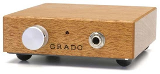
For those of you who are not familiar with the Grado RA1 headphone amplifier, it is well regarded, runs off of two 9V batteries, is housed in a beautiful mahogany enclosure and retails for about $350US. A stock photograph the Grado RA1 is shown below.

Grado RA-1 Headphone Amplifier
Recently I had the opportunity to visit and listen to his Grado SR225 / RA1 combination. Of course I brought along my little pocket CMoy headphone amplifier! :)

We both did some blind listening and in the end we pretty much had the same listening impressions. We thought that both the CMoy and RA1 amps sounded excellent and fairly similar, but we both gave a slight edge to the DIY CMoy amplifier. We were both a little surprised, considering you can build a CMoy for about $20 or buy an already built one for about $40 on eBay, yet the Grado RA1 rings in at $350.

After a few Google searches, we found that others had reported similar listening impressions between the two amps. That being, they both sound very good, with similarities between the two and the slight edge going to the CMoy. But what I found most interesting were these two sites, one which showed the dissection of a Grado RA1 headphone amplifier and the other which also took apart and upgraded the Grado RA-1. The sites provide pictures of the inner details of the RA1 and also a schematic for the amplifier section. The schematics below show the both the Grado RA-1 and CMoy headphone amplifiers.


Schematic - Grado RA1 Headphone Amplifier


Schematic - CMoy Headphone Amplifier

Both the Grado RA1 and CMoy designs use a basic non-inverting amplifier circuit using an operational amplifier (opamp). For my CMoy, the opamp used was a OPA2132PA (Burr-Brown) which retails for about $5 and for the Grado RA1 uses a JR4556 that retails for about $0.50. Despite the fact that the JR4556 is a low cost opamp, the RA1 sounds decent, but not as good as a properly implemented CMoy headphone amplifier - (DIY lets you choose the gain setting).


Gainclone Amplifier(LM3875)

Mark has been hanging out in the kitchen and has put together the Gainclone amplifier shown below.

LM3875 Gainclone Chip Amplifier
For the enclosure, Mark has used a heavy cast aluminum cooking pan and a massive wooden cutting board. The amplifier is based around the LM3875 chip (power opamp) and uses point-to-point wiring. The amplifier follows the
"rigid and compact" approach of the 47 Laboratory Gaincard amplifier. A rigid enclosure is used to reduce resonance and vibration while a short signal path, feedback loop and minimal parts (compact) are used to preserve information. The schematic of the three resistor amplifier is shown below.

LM3875 Gainclone Chip Amplifier Schematic
Keep cooking Mark, as I look forward to more of your projects. See the project page for full details of Mark's Synergy - LM3875 Gainclone Chip Amplifier Project.

Tripath TA2020 chip and diy class T-amplifier kit(AMP6)

It has been a long while since I added one of my own projects to the diyAudioProjects.com website. I had actually finished this project back in the summer, but never got around to pulling together a web page for it until now. Over the past few years I have read a lot of good things about Class-T Amplifiers (T-Amps). For those who are unfamiliar with T-Amps, the chip manufacturer (Tripath) describes the Class-T amplifier chip as one that can offer both the audio fidelity of Class-AB and the efficiency of Class-D.

DIY Class T Amplifier Kit (T-Amp)
I decided to try a kit from 41hz.com as they are priced very well and I have read several good reviews of their T-Amp kits. I opted for the AMP6 kit which uses the popular Tripath TA2020 chip. The kit was only $39 and fairly simple to put together.

For the enclosure, I used a prefabricated aluminum chassis. The results are a little industrial looking, but heck, I am interested in the sound quality, not the enclosure.

Finished AMP6 T-Amp Kit
A lot of people describe T-Amps as having a "warm tube like sound". I didn't think so. I did not like the sound when mated with high efficiency fullrange speakers. However, with more traditional speakers (2 and 3 way) I was very pleased with the performance of the little AMP6 (about 12W into 4 ohms and only 7W into 8 ohms). It provided accurate tight bass and detailed mids and high. While I prefer the sound from my DIY LM3886 Chipamp (gainclone) Kit, the AMP6 is a solid preforming small amplifier with an excellent price to performance ratio.

power supply and enclousre for diy op amp based preamplifier

INTRODUCTION
Rod Elliott's High Quality Audio Preamp (Mk II) which is a two stage preamp with balance control seemed like a good choice.

DIY PREAMP AND POWER SUPPLY

Two small pc proto boards (Radio Shack 276-159 / Dick Smith H5601) were used to accommodate all components. Metal film polypropylene capacitors were used in the signal path. It would have made the whole project easier by using physically smaller caps but for me the sound was a priority. For the power supply I used a 1.2A 18V regulated SMPS wall wart. I definitely do not need 1.2A, but I wanted a gutsy supply. Two 1k 0.5W resistors make up the "virtual ground" split supply. 220 uF low ESR capacitors and 0.1 uF decoupling capacitors are used for channel. This simple supply configuration works very well and is dead quiet.

DIY OPA2134AP Linestage Preamp PCB
PREAMP ENCLOSURE
The case only measures 115 X 90 X 55 mm (same size enclosure that I used for my Nanoo LM3875 Gainclone) and placing all the components in this tiny space, including a dual gang volume control and balance control was going to be tough. Unless you enjoy working in ridiculously small spaces and/or you are masochistic, build this preamp in a bigger case. Even a slightly bigger enclosure would be better. For the finish I use an acid etch primer, allowed a few days drying and then the spray color over the top. This was the same technique used with the big red caps on the Synergy Roasting Pan LM3875 Chip Amp / Gainclone.


DIY OPA2134AP Linestage Enclosure Front
DIY OPA2134AP Linestage Enclosure Back
RESULTS

I have used the preamp as a front end to my S-5 Electronics K-12 Tube Amplifier. The test setup comprised a NAD C542, modified bookshelf speakers and DIY Silver Interconnect Cables
. The preamp added nothing and took away any CD player/ Valve power amp miss-match. For that reason I have named it Neutrino. The balance control has a very wide sweet spot and the volume control was non-twitchy, linear and easy to use. A very inexpensive project but it feels odd to build something that adds and removes NOTHING audibly in a cute box.

TDA2050v ic used to built hi-fi chip amplifier(chipamp)

Tags
Thomas from Germany has put together a build log of his recent DIY TDA2050 Hi-Fi Chip Amplifier (chipamp) build. The chipamp project is built around a single chip - the TDA2050V integrated circuit (IC) which is produced by STMicroelectronics. The TDA2050 chip is capable of producing about 25W of output into 8 ohms with 24V power supply rails. Like most chipamp projects, the circuit is very simple and can easily be constructed on perfboards.

TDA2050 Chipamp Circuit on a Perfboard
The power supply is also constructed on a perfboard. For the power supply Thomas uses a 120VA torroidal transformer with dual 18V secondaries and generally followed the "snubberized" Gainclone power supply design by CarlosFM with 10,000 uF per rail.

DIY TDA2050 Mini Gainclone Chipamp

For the enclosure Thomas used a Hammond satin black steel 12" x 8" x 3" chassis (Model 1441-24). The amplifier controls including a headphone output are on the front.

Finished DIY TDA2050 Chipamp

Thomas reports that the chipamp produces very good sound and that the small amp can hold it own against various high quality amplifiers that he has used.These chipamps are simple to build, low-cost and when properly implemented can deliver very good fidelity. If you are looking for a project to try out, give one a try.

headphone amplifier 6418 sub-miniature tube preamp

We often get questions asking about suitable vacuum tube (valve) kits for beginners or first time DIYers. Aside from the fact that vacuum tube audio kits are generally expensive, there is also the safety concern that most tube circuits operate with potentially lethal voltages. Mark in Australia found the following 6418 tube preamplifier and headphone amp kit which is an exception - it is inexpensive and can operate from single 9V battery.

6418 sub-mini Tube Preamp / Head Amp Kit
The tube preamp / headamp kit is from Oatley Electronics in New South Wales Australia and based around the Raytheon JAN6418 sub-miniature valve (tube) and an IC. The K272 Stereo Tube Preamplifier – Headphone Driver kit cost $27AU (~$23US – August 2009). The kit is complete including a printed circuit board (PCB) which makes for easy assembly but you will need to provide your own enclosure. The kit only consumes about 12mA at 9V and can be powered with a single 9V battery making this a safe and ideal kit for those who are new to vacuum tube electronics.

6418 Tube Preamp / Headphone Amp Kit
The photo above is a build of the kit using the supplied parts. Since the 6418 tube are extremely microphonic and will "ring" if they are subjected to vibrations rubber grommets are used to help damp the tubes. Mark has built a number of these kits now including a few with upgraded parts (metal film resistors, polypropylene film inter-stage capacitors and a Burr-Brown OPA2134 op-amp). The photo below is a tube preamp in a plastic ABS enclosure using the kit and upgraded components.

6418 Tube Preamplifier Kit
Mark reports that the kit performs well and sounds good. The bandwidth is very wide, the -3dB points are 10Hz and 50kHz. As a preamp there is good depth, wide breadth and sharp detail revealing fine recorded detail with no hard edges. The photo below shows the kit in a plastic enclosure being used as a portable headphone amplifier.

6418 Tube Headphone Amplifier Kit

LME49710 based high end audiophile headphone amplifier

Kelvyn Shaw in the UK sent us a note with a link to his latest DIY Audio Project - a High-End Headphone Amplifier. The headphone amp is made using only premium components and built around the National Semiconductor LME49710 high-performance Hi-Fi operational amplifier which is noted as costing 20 times more than your typical op-amp.

DIY High-End Headphone Amplifier PCB
Kelvyn notes that the amplifier "Uses only the finest audiophile quality components that have been carefully selected with no expense spared". Power is supplied through a regulated dual rail power supply using a low noise toroidal transformer. The amplifier is housed in a black anodized aluminum enclosure with a heavy duty clear anodized aluminum front panel. An Alps Blue Velvet potentiometer is used for the volume control.

DIY High-End Headphone Amplifier
DIY Audiophile Headphone Amplifier


Excellent sound produced by Oatley Electronics K272A tube based Headphone Amp


"... The K272A/Grado combination produced excellent sound: a fne bass (powerful and deep but not overblown), detailed mid-range, sweet top-end. Tonal colors of string instruments and vocals of male and female soloists were naturally represented. Many small, previously unnoticed details of recordings were revealed."

"In direct A/B comparisons, the K272A sounded better than the G4OEP (3/08 aX, p. 36) and even slightly better than the Stor class A amplifier (6/03 aX, p. 30)."

"For the asking price of 30 Australian dollars, the K272A is an absolute bargain. And it does not involve any dangerous voltages."

the HiFi test setup and the fine wire audio cable shoot out

The HiFi Test Set-up
The test set-up used to evaluate the cables consisted of an upgraded Oppo 980H, a diy build of the Nelson Pass B1 buffer preamp, a diy 6AS7 SET power amplifier and Fostex FE206En drivers in a back loaded horn enclosure. I selected a number of test tracks which I thought had enough variation to exhibit any great cable sonics. To make sure I was not biased I enlisted the aid of a golden eared friend, Ron from the Melbourne Audio Club. He also brought along his test tracks.

Oppo 980H, Pass B1 Buffer, 6AS7 SET, FE206En Rear Horn

Cable Shoot-Out
We played through about half a dozen test tracks using both short and long runs of #1, Air-spaced Finewire RCA cables and set of #6, Air-spaced Finewire speaker cables which were 2 m in length. My SET amp produces only 3W so fine wire speaker cables will work with this amp. But will it be the best sound we can get?

What we found was in just three test tracks we could listen for:
  • The shimmer in cymbals
  • The breathiness in flute and its balance against a harp
  • The rich tone of a fully fleshed violin
Of course this in no way covers every tone or nuance of every sonic effect listenable on any recording but I feel it was enough to highlight the main differences in the cables.

After listening with the cable combination above we swapped the #1, Air-spaced Finewire RCA cables for a cheap $2 store bought RCA cable. Some areas of the test music actually improved. The sound stage appeared to widen or was it just smeared between the speakers. The violin appeared to fatten-up or was the detail just lost. Ron and I then, cable by cable, started putting back both sets of #1, Air-spaced Finewire RCA cables and the other various cables that we had on hand.

We started with the short #1, Air-spaced Finewire RCA cables which lead from the CD player to the preamplifier. We also introduced my twisted version of the WWW interconnect cables and also my braided Silver Highway RCA cables. I have built many sets of these high-purity silver wire RCA cables and everyone who has used them claims they are excellent. At each stage we re-listened to the three test tracks.

What We Found
Without boring the pants off you with every detailed cable swap this is what we found.
  • The #1, Air-spaced Finewire interconnect cables work best between the CD player and the preamp (short cable, 150 mm long)
  • My diy Silver Highway RCA cables (900 mm) worked best between the preamplifier and power amplifier. They worked better than my twisted WWW cable, but only slightly better.
  • Multi-stand heavy OFC speaker leads (3 m long) with heavy brass banana plugs only just outperformed the #6, Air-spaced Finewire speaker cables (2 m long).
Cable Measurements
Ron brought his dedicated capacitance and inductance meter and here are the cable measurements:

RCA Cables
#1, Air-spaced Finewire (short): 30 pF, 8 uH, 0.4 ohm
#1, Air-spaced Finewire (long): 30 pF, 13 uH, 1.5 ohm
Twisted cables (destination end): 13 pF, 8 uH, 0.4 ohm
Twisted cables (source end): 138 pF, 10 uH, 0.4 ohm
Silver Highways (900 mm): 71 pF, 2 uH, 0.3 ohm
$2 Generic RCA (1000 mm): 370 pF, 0.1 uH, 0.1 ohm

Speaker Cables
#6, Air-spaced Finewire (2 m): 25 pF, 17 uH, 1.5 ohm
Multi-stand heavy OFC (3 m): 210pF, 1uH, 0.1 ohm

Note: The twisted cables comprise of three wire wrap wires, only two of which are terminated at the destination end. I believe the 30 pF of capacitance for some of #1, Air-spaced Finewire cables is due to the cheap RCA plug that was used. The twisted cables had only 13 pF for the destination end which only has two wires connected. Also the RCA used on the twisted cable were heavy weight high-end types and I believe low capacitance types.

Just a Cable Suggestion
It is worth while trying different cables, weather you make your own or buy them off the shelf. If possible, try borrowing some friend’s cables before outlaying hundreds of dollars on expensive ones. Different combinations of cables can work better than just one cable type used throughout your system. If nothing else, cable swapping and comparison will fill in an afternoon and you may enjoy the music along the way.

literature specification for new German made Voxativ Ampeggio single-driver rear-loaded horn speakers

Tags
The hand built rear-loaded horn enclosures are built in a collaboration between Voxativ and the famous German piano factory Schimmel Pianos. The cabinet surface is finished with a minimum of 13 applications of hand polished lacquer covered in real piano lacquer. The finish on the loudspeakers was simply amazing.


The product literature lists the following specifications for the Ampeggio:

Frequency Response: 38 - 20,000 Hz
Sensitivity: 101 dB / 1w / 1m
Impedance: 10 ohms
Dimensions (W x H x D): 16" x 43" x 14" (40 x 110 x 35 cm)
Weight: 121 lbs (55 kg)
Cost: $29,750US


The lone transducer used in the Ampeggio is the Voxativ AC-3X, which is their largest neodymium driver and unavailable for purchase. The drivers suspension is made from goat leather. The loudspeaker systems does not use any crossover components.


A Don Garber Fi WE421A ($3275) single-ended triode amplifier (a single dual triode), putting out just 5 watts per channel was used to drive the Ampeggio speakers. With a sensitivity of 101dB it was plenty loud. The high sensitivity and easy 10 ohm loads means these speakers will mate very well with low power SET amplifiers. The Ampeggio speakers sounded every bit as wonderful as they looked. Open, dynamic, excellent clarity and plenty of detail.

Interesting Lamb skin made drivers(Feastrex NF-5 and NF-5ex Drivers at SSI 2011)

Tags


We are big fans of single full-range driver loud speakers so we were excited to check out the Feastrex drivers. Michael Tang of Mike Tang Audio is importing the Japanese Feastrex NF-5 and NF-5EX drivers into Canada and had them on display at the show.


The 5" Feastrex NF-5 ($2000CDN, shown above) uses a large Alnico magnet. The handmade cones are made from Japanese Washi paper (a higher density fibrous paper) which is impressed in a spiral pattern with embossed ridges. The drivers surround is made from lamb skin.


The 5" Feastrex NF-5ex ($3000CDN, shown above) uses the same Washi paper cone and a lambskin surround, but with a motor that uses a field-coil magnet (electromagnet). The field-coil magnet can be operated between 10 and 17V dc. Changing the voltage allows you to change the damping of the driver. Michael uses a 12V car battery for the field-coil magnet. 16 ohms, 95 dB, 35 to 25,000 Hz (+/- 3dB).


A Mastersound Compact 845 SET powered the 5" Feastrex NF-5 drivers which were housed in a bass reflex enclosure (enclosure plans from Feastrex, shown below), no passive filters were used. The speakers sounded excellent, wide soundstage and impressive depth. The single drivers delivered superb clarity with vocals to die for.

Michael indicated that he is working on a transmission line enclosure design for use with the Feastrex NF-5 and NF-5ex drivers which he plans to have ready for the TAVES (Toronto Audio and Video Entertainment Show) this fall.

characteristics of Stereo Encoder(Pira CZ) for FM broadcasting

Tags

This stereo encoder is a halfway between analogue and digital processing. It combines the best from both domains to provide high-quality and easy to build device. The sampling frequency used in this stereo encoder is 97 times (!!!) higher than the pilot tone frequency. This makes very easy to reject all spectral residues around the sampling frequency without affecting the main signal characteristics. Using of a microcontroller allows to build this stereo encoder with reduced part count and get excellent results in real operation.

This stereo encoder advisedly does not contain any preemphasis circuit. Remember the key fact: a compressor/limiter/clipper device must be always present between the preemphasis circuit and the stereo encoder or modulator. Only this configuration ensures loud sound without exceeding the maximum frequency deviation limit (75 kHz). The stereo encoder is designed to provide really good sound. This always needs to use the compressor/limiter/clipper device where the preemphasis is precisely assured.This stereo is suitable for this task.

Characteristics:
  • Signal overshooting prevention (overshooting max. 10 %)
  • Low noise and distortion
  • No adjust (only pilot tone level and output level)
  • High channel separation and spectral purity in common operation
  • RDS input and pilot sync. output makes easy to connect any RDS encoder
  • Microcomputer controlled, hex file provided for free
  • All parts are easy to buy (incl. crystal)
  • S:discovercircuits.com

design for amateurs 40A stabilized power supply circuit

design for amateurs 40A stabilized power supply circuit

This power supply is designed for amateurs, and has been in operation for over 10 years. Its design is very simple and practically immune to RF. It brings together the individual pieces, is the most expensive part of 600VA toroidal transformer, which can be replaced by another with different characteristics, in the case of a voltage between 17 ~ 20V power and right for our needs.

Reference voltage of 7.5 V Zenner diode (6V8 ~ 8V2), shall apply to Q2, which compares the input resistive voltage divider consisting of R5, R6 and VR2, steering Darlington amplifier Q3, which is responsible for driving the output stage, which consists of a driver in Q4 and 4 2N3771 NPN power transistor, which can be mounted directly on the heat sink without insulation, since it is a collector grounded.

The source has a current limit (Q1), adjusted by VR1 and overload LED (DL2) and full protection against short circuits, with zero consumption in case of short circuit can be maintained indefinitely in this state without danger.

(Please note that due to the strong power of the power supply with a casual a short length of cable, high or small section that is strong enough to not exceed the maximum current of 40A. Can not be considered a short circuit and cause the supply of a power supply large amounts of energy).

active rectifier (D1, D2) is recommended for a type of cathode metal screw is on the ground, install a heat sink large enough block. As power transistors using a hedgehog as high as possible, without being isolated as above, can be part of the window of an aluminum frame. We also recommend using mechanical ventilation with the thermostat.

PIC16F688 Based Digital Voltmeter with a PIC mictocontroller

Circuit diagram

This project describes how to make a digital voltmeter with a PIC microcontroller. A character based on HD44780 LCD display is used to measure voltage. The PIC microcontroller used in this project is PIC16F688, which has 12 I / O pins of which 8 can be used as analog input channels to the built-in 10-bit ADC. The measured voltage is fed to one of eight analog channels.

The reference voltage for the AD conversion is chosen to be the supply voltage Vdd (+5 V). A resistor divider network is used to end the inning with a map of the range of input voltage range of ADC input voltage (0-5 V). The technique can show that the input voltage from 0 to 20 V, but can be expanded with an appropriate choice of resistance and make the calculation described below.

Since the PIC port can not be directly 20V input, the input voltage is reduced by using a resistor divider network simple. The resistors R1 and input voltage range R2-range of 0-20V to 0-5V, before being implemented in PIC16F688 channel analog input AN2. 5.1V zener diode connected in parallel between the port pin AN2 and earth provides protection to the PIC pin input voltage is accidentally beyond 20V. The LCD screen is connected to the 4-bit mode, and the head of CPSI makes firmware development easier than you can reprogram and test the PIC while it is on. When you’re happy and you want to transfer the circuit of the test card to a PCB or prototyping board for general purposes, it is not necessary ICSP header.
S:

Advertisement