Brightness Controller Circuit For Small Lamps and Leds

Tags


This device was designed on request; to control the light intensity of four filament lamps (i.e. a ring illuminator) powered by two AA or AAA batteries, for close-up pictures with a digital camera. Obviously it can be used in other ways, at anyone's will.IC1 generates a 150Hz square wave having a variable duty-cycle. When the cursor of P1 is fully rotated towards D1, the output positive pulses appearing at pin 3 of IC1 are very narrow.
Bulb LP1, driven by Q1, is off as the voltage across its leads is too low. When the cursor of P1 is rotated towards R2, the output pulses increase in width, reaching their maximum amplitude when the potentiometer is rotated fully clockwise. In this way the bulb reaches its full brightness.


Parts:

P1 = 470K
R1 = 10K
R2 = 47K
R3 = 1.5K
C1 = 22nF-63V
C2 = 100uF-25V
D1 = 1N4148
D2 = 1N4148
Q1 = BD681
B1 = 2xAA cells in series
IC1 = 7555 or TS555CN
LP1 = 1.5V 200mA Bulb
SW1 = SPST Switch


Notes:

* LP1 can be one or more 1.5V bulbs wired in parallel. Maximum total output current allowed is about 1A.
* R2 limits the output voltage, measured across LP1 leads, to 1.5V. Its actual value is dependent on the total current drawn by the bulb(s) and should be set at full load in order to obtain about 1.5V across the bulb(s) leads when P1 is rotated fully clockwise.

7 segment rolling display using PC

Tags


It is very interesting and convenient to be able to control everything while sitting at your PC terminal. Here, a simple hardware circuit and software is used to interface a 7-segment based rolling display. The printer port of a PC provides a set of points with some acting as input lines and some others as output lines.


http://www.electronic-circuits-diagrams.com/computersimages/4.gif


Some lines are open collector type which can be used as input lines. The circuit given here can be used for interfacing with any type of PC’s printer port. The 25-pin parallel port connector at the back of a PC is a combination of three ports. The address varies from 378H-37AH. The 7 lines of port 378H (pins 2 through 8) are used in this circuit to output the code for segment display through IC1. The remaining one line of port 378H (pin 9) and four lines of port 37AH (pins 1, 14, 16, 17) are used to enable the display digits (one a time) through IC2. The bits D0, D1 and D3 of port 37AH connected to pins 1, 14 and 17 of ‘D’ connector are inverted by the computer before application to the pins while data bit D2 is not inverted. Therefore to get a logic high at any of former three pins, we must send logic 0 output to the corresponding pin of port 37AH. Another important concept illustrated by the project is the time division multiplexing. Note that all the five 7-segment displays share a common data bus. The PC places the 7-segment code for the first digit/character on the data bus and enables only the first 7-segment display. After delay of a few milliseconds, the 7-segment code for the digit/character is replaced by that of the next charter/digit, but this time only second display digit is enabled. After the display of all characters/digits in this way, the cycle repeats itself over and over again. Because of this repetition at a fairly high rate, there is an illusion that all the digits/characters are continuously being displayed. DISP1 is to be physically placed as the least significant digit. IC1 (74LS244) is an octal buffer which is primarily used to increase the driving capability. It has two groups of four buffers with non-inverted tri-state outputs. The buffer is controlled by two active low enable lines. IC2 (75492) can drive a maximum of six 7-segment displays. (For driving up to seven common-cathode displays one may use ULN2003 described elsewhere in this section.) The program for rolling display is given in the listing DISP.C above. Whatever the message/characters to be displayed (here five characters have been displayed), these are separated and stored in an array. Then these are decoded. Decoding software is very simple. Just replace the desired character with the binary equivalent of the display code. The display code is a byte that has the appropriate bits turned on. For example, to display character ‘L’, the segments to be turned on are f, e and d. This is equivalent to 111000 binary or 38 hex. Please note that only limited characters can be formed using 7-segment display. Characters such as M, N and K cannot be formed properly

LM317 based Lamp flasher circuit with explanation

Tags


Here is a very useful lamp flasher circuit using the famous adjustable voltage regulator IC LM317T. LM317 can source up to 1A of current and so up to 12W lamps can be used with this flasher. Such a circuit finds huge application in automobiles. The frequency of the flashing depends on the value of resistors R1 to R3 and capacitors C2 to C4.With the given values; the flashing rate is around 5 flashes per second.


Notes.

* The circuit can be assembled on a Vero board.
* Use 12V DC for powering the circuit.
* Use a proper heat sink with the IC1.
* Switch S1 can be a ON/OFF switch.

8 function christmas lamp circuit with explanation

Tags


This is a gift for you for the on coming Christmas.This is a 8 function christmas lamp so yopu can use this to decorate your xmas tree or your crib.


Note

# L1 to L4 can be 230V/40W lamps.

# Heat sinks are recommended for the SCRs.

# H1 to H4 can be TYN612 SCRs.


SO Happy Christmas for you

220v Flasher for the Christmas tree circuit

Tags


This is wonderful circuit for all because you can use this circuit to decorate your Christmas tree with 220v bulbs.So make a most attractive Christmas tree for this winter.


Parts:

C1 1000µF 25V Electrolytic Capacitor
D1-D4 1N4007 1000V 1A Diodes
D5 P0102D 400V 800mA SCR
Q1 BC327 45V 800mA PNP Transistor
Q2 BC337 45V 800mA NPN Transistor
R1 100K 1/4W Resistor
R2,R5 1K 1/4W Resistors
R3,R6 470R 1/4W Resistors
R4 12K 1/4W Resistor
PL1 Male Mains plug
SK1 Female Mains socket


Note

# You have to use high Gate-sensitive SCRs for the proper operation.

# A recommended Triac type is the ubiquitous TIC206M (600V 4A) but many others can work.

Delayed switch for Bedroom lamp circuit with explanation

Tags


Here I have introduce a new circuit through this you can switch off your bed room lamp with some delay.so I suppose this may be so useful circuit for you.and also after attaching a relay for this circuit you can use this as a delay circuit.This gives 15 second delay


Parts:

C1 330nF 400V Polyester Capacitor

C2 100µF 25V Electrolytic Capacitor

C3,C5 10nF 63V Polyester or Ceramic Capacitors

C4 10µF 25V Electrolytic Capacitor

R1 470R 1/2W Resistor

R2 100K 1/4W Resistor

R3 1M5 1/4W Resistor

R4 1K 1/4W Resistor

D1,D2 1N4007 1000V 1A Diodes

D3 BZX79C10 10V 500mW Zener Diode

D4 TIC206M 600V 4A TRIAC

Q1 BC557 45V 100mA PNP Transistor

IC1 7555 or TS555CN CMos Timer IC

SW1 SPST Mains suited Switch

Note

# The delay time can be changed, changing R3 and/or C4 values.
Taking C4=10µF, R3 increases timing with approx. 100K per second ratio. I.e. R3=1M Time=10 seconds, R3=1M8 Time=18 seconds. Do test and see it.

230 V Christmas lights circuit with explanation

Tags


Christmas is getting near so I thought to give you very useful circuit.The impotent thing of this circuit is it operates from 230v.Here Time to time two sets of 230v bulbs light up.Actually you can use this one for your Christmas tree or for your crib.you can attach 5w 12 bulbs for 1 side.This circuit needs three power supplies as 6v, 12v and 230v.To supply 12v and 6 v use 300mA power supply.You can change the speed of lights by using 1M preset.


Note

# Use High amp really
# Be careful when you work with 230v

Wesak Flasher with 6 Bulb circuit with explanation

Tags


Wesak festival is getting near.So I decided to give you a very useful circuit diagram this circuit can drive 650Watt (Lamp 220V ) per Lamp channels.By using VR1 you can control the speed of your lamps.Here I have used very famous Ic 4017 and Ic NE 555.You can directly connect this circuit for 230V.


Note

# This circuit is 230V circuit so this is not good for kids

# don't exceed 650W

LED Flasher circuit Diagram with explanation

Tags


This is Multi vibrator circuit diagram H ere you can attach up to 4 LEDs.I suppose this circuit will be so useful for all.You can use this circuit to decorate your Wesak Lanterns


Note

# This circuit can be operated with 3 to 9V

The Joule Thief circuit with explanation

Tags


This circuit is called " The Joule Thief" Because this circuit can light up LEDs with low voltage that is the reason for this.If you have drained batteries you can lite up a LED by using this circuit.Now I thing you can understand how much important this circuit is


Simple Christmas star from multivibrator Circuit Diagram

Tags


This is so simple circuit But you can use this circuit as a Christmas star.Here I have used famous transistor 2N3904.If you are unable to find this transistor you can use D400 instead of that.This circuit operates with 9V.I used this circuit for the last Christmas If you used Blue color LED s It would give inexpressible attraction.


Note

# If you want to change the speed of this circuit You can do it by changing the values of 10uf and 100k

# This circuit can be operated with 9V power supply

# Fix this circuit on a pcb

Blinking LED Circuit Diagram with explanation

Tags


This is a blinking LED circuit diagram.Here I have used common IC NE555.If you want to change the speed of this circuit you can change the value of R2.Then you can do that.


Note

* Use a PCB to build this circuit
* You can operate this circuit with 9V

Simple Flaher Circuit Diagram (24V) circuit

Tags


This is a simple flasher circuit diagram.Some people can't use normal circuit diagrams due to 24V batteries of there Vehicles.Here I Have introduced 24V circuit diagram for you all.Here I have used simple circuit diagram.It is multivibrator circuit .Here I have used famous transistor 2N3055.


Note

# Build this circuit on a PCB
# This circuit can be operated with 18V-24V

powerful pocket Headphone Amplifier circuit Diagram

Tags


Lots of guys asked me about Pocket head phone amplifiers.This circuit will be a good answer for that.Here I have used very common IC OPA134.You can power this circuit with 9V battery.


Note

# Design this circuit on a PCB
# use 9V to power this circuit

IR Audio Transmitter circuit with explanation

Tags


This is very useful circuit you can transmit audio signals by using this circuit.You can send signals for about 4m.Q1 can be PNZ154, PNA1605F, BPW77NA or BPW85.


Note

# this circuit can be operated with 9V power supply

Simple Audio power meter circuit with explanation


This is simple audio power meter.When you use high power speakers this circuit is so important Because you can keep your speakers without burning.Here When the speaker out puts 1W green color LED will light up,for 1.5W you will be able to see orange color,When speaker out puts more than 3W you will be able to see red color.


Note

# The power levels mentioned are valid for 4-Ohm speakers. For 8-Ohm speakers you have to divide all the resistor values by two

# this circuit cant drive more than 40W continuously.

# If you want more LEDs you can attach LEDs as the same way

80-M AMATEUR RADIO TRANSMITTER

Tags


1N3044B,MPF910,MTP12N10 circuit : 80-M AMATEUR RADIO TRANSMITTER


This transmitter consists of a keyed crystal oscillatoridriver and a high efficiency final, each with a TMOS Power FET as the active element. The total parts cost less than $20, and no special construction skills or circuit boards are required.

The Pierce oscillator is unique because the high CRSS of the final amplifier power FET, 700 - 1200 pF, is used as part of the capacitive feedback network. In fact, the oscillator will not work without Q2 installed. The MPF910 is a good choice for this circuit because the transistor is capable of driving the final amplifier in a switching mode, while still retaining enough gain for oscillation.

To minimize cost, a readily-available color burst TV crystal is used as the frequency-determining element for Q1.An unusual 84% output efficiency is possible with this transmitter. Such high efficiency is achieved because of the TMOS power FET's characteristics, along with modification of the usual algorithm for determining output matching.

1.8-1.9 MHz VFO

Tags


MPF102,1N914,2N2222 circuit : 1.8-1.9 MHz VFO

Series-tuned Clapp oscilla-torusing high-impedance JFET at has good fre-quency stability. Diode stabilizes bias. Air variable C1 provides frequency spread of exactly 100 kHz. L1 is 25-58 μH slug-tuned (Miller 43A475CBI). L2 is 10-18.7 μH slug-tuned .

74HC240 Qrp Transmitter.


Description.

The ARRL HB describes an experimental 0.5W transmitter that uses a 74HC240 octal inverting buffer. One section is used as a fundamental frequency oscillator, four sections are used as an amplifier, while three sections are grounded, and unused. The three unused sections can be put to use in further expansion into a TCVR. Q1 is used to key the transmitter, while the 7808 provides a stable 8V DC supply. THe IC will dissipate heat, and a heat sink should be glued onto it using epoxy. The low pass filter is standard, and the values for some HF bands are given in the table above. This design forms the basis of a minimal QRP TCVR that I am developing, as part of my education in electronics.

http://www.qsl.net/5z4ft/74hc240qrp.html

10-M DSB QRP TRANSMITTER WITH VFO

Tags

10-M DSB QRP TRANSMITTER WITH VFO


NE602 circuit : 10-M DSB QRP TRANSMITTER WITH VFO
NE602
NE602 circuit : 10-M DSB QRP TRANSMITTER WITH VFO
NE602
The three schematics represent three building blocks for a 10-meter SSB transmitter. Or these blocks can be used separately as circuit modules for other transmitters. The VFO board uses an FET transmittal oscillator, the VFO signal is mixed in an NE602 mixer and is amplified by Q2 to a level suf-ficient to drive an SBL-1 mixer in the transmit mixer stage (+7 to +10 dBm). In the balance mixer/modulator board, an 11-MHz crystal oscillator drives a diode balanced mixer. Audio for mod-ulation purposes is also fed to this mixer. The DSB signal feeds a 28-MHz BPR The 1-W amplifier board consists of a 3-stage amplifier and transmit/receive switching circuitry.

NiMH Battery Charger Here is a simple battery charger for the Nickel Metal Hydride battery that requires current regulated charging. The charger pr

Tags
Here is a simple battery charger for the Nickel Metal Hydride battery that requires current regulated charging. The charger provides 140 mA current for quick charging of the battery.Power supply section consists of a 0-18 volt AC 1 Ampere step-down transformer, a full wave bridge rectifier comprising D1 through D4 and the smoothing capacitor C1. Current regulation is achieved by the action of R1,R2 and the Epitaxial Darlington PNP transistor TIP 127. Resistor R1 keeps the charging current to 140 milli amperes. LED and resistor R2 plays an important role to control the base current of T1 and thus its output.


Around 2.6 volts drop develops across the LED which appears at the base of T1. Emitter – base junction of T1 drops around 1.2 volts. So 2.6 – 1.2 volts gives 1.40 volts. So the current passing through R1 will be 1.40 V / 10 = 0.14 Amps or 140 Milli Amps. The LED act as the charging status indicator. LED lights only if the battery is connected to the output of circuit and the input voltage is normal.

Read more: http://electroschematics.com/6073/nimh-battery-charger/#ixzz1HL7dzmz5

How to make foxhole radio receiver (with no batteries) Foxhole radio receiver or Crystal receiver is a form of radio that does not operate on local

Tags

How to make foxhole radio receiver (with no batteries)

Foxhole radio receiver or Crystal receiver is a form of radio that does not operate on local oscillator, which makes it hard to be detected by other electronic device. One of the most interesting thing of Foxhole radio is that it could be operated without the use of batteries, as it is powered solely by the radio waves through its long wire antenna.

Foxhole radio was (supposedly) popular during World War II because it enabled the GI to receive radio broadcast in the middle of the war, particularly in France as the Germans has outlawed the use of radio by civilians, thus the American GI need to build their own receiver to receive broadcasts. Typical component of foxhole radio during those days are : a period razor blade (not the newer galvanized one), carbon (obtained from pencil) and some copper wire with woodblock or cardboard as its base.

http://please.name.my/302/how-to-make-foxhole-radio-receiver-with-no-batteries.html

W1FB 6M RF Preamp

image

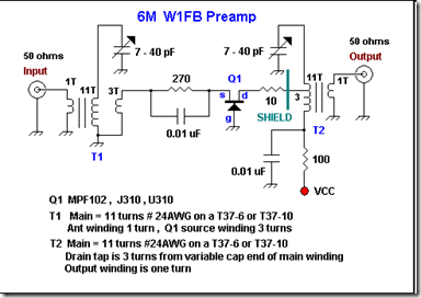
Here is a schematic sent to me by W1FB many years ago. It is very similar to a 6M two-stage preamp that he published in QST in the mid eighties. Doug really favored the grounded gate FET for narrow band preamps. His published work is replete with examples of them on just about every band. I built that amp and remember getting about 10 dB gain, which is all that I wanted for the 6M direct conversion receiver using a diode ring detector that I was building. The great feature of the amp is that it combines a band pass filter and preamp in one. I lost the original schematic that Doug sent me but was delighted to see that I made a bitmapped drawing of it on a floppy disk that was recently re-discovered when we were moving an old desk. The shield shown in the schematic was a small piece of grounded ,double sided PC board in which, I made a small chamfered hole in to pass the lead going to the T2 tap. The shield, along with very short component leads will help minimize parasitic oscillations. The T2 tap is 3 turns down from the end of the T2 main winding that connects to the variable capacitor. Doug specified T37-10 cores for the inductors, but I substituted T37-6 cores and used the same number of windings as specified for the T37-10 core inductors. It worked fine.

http://www.qrp.pops.net/preamp.asp

Building a radio in 10 minutes.

Tags

http://sci-toys.com/scitoys/scitoys/radio/ten_minute_radio.html

For our 10 minute radio, we will need these parts:

  • A ferrite loop antenna coil

    In our other crystal radios we wound the coil by hand. In this project we use a much smaller coil with a ferrite rod inside, from our catalog. The ferrite rod allows the coil to be smaller, and it can be moved in and out of the coil for coarse tuning.

  • A variable capacitor (30 to 160 picofarads)

    We carry this in our catalog. You can also find them in old broken or discarded radios.

  • A Germanium diode (1N34A)

    We carry this in our catalog.

  • A piezoelectric earphone

    Also in our catalog.

  • Two alligator jumper wires

    We use alligator jumper wires here for convenience. They are used to connect the ground and antenna wires to a good ground and a long wire antenna. We carry these in our catalog.

  • About 50 to 100 feet of stranded insulated wire for an antenna.

    This is actually optional, since you can use a TV antenna or FM radio antenna by connecting our radio to one of the lead-in wires. But it's fun to throw your own wire up over a tree or on top of a house, and it makes the radio a little more portable.

  • A block of wood or something similar for a base

2N3055 based High Current Power Supply Circuit

This is a unregulated dc power supply circuit which have ability to handle high current load.
High Current Power Supply Circuit with 2N3055
Component parts:
R1_________ 680 Ohm 1/4 Watt Resistor
C1_________ 20,000 - 50,000uF 20-40 Volt Capacitor
C2, C3_____ 100uF/50 Volt Capacitor
C4_________ 0.1uF 50 Volt Capacitor
C5_________ 0.01uF 50 Volt Capacitor
D1_________ Zener Diode
Q1_________ 2N3055 Or Other
T1_________ Transformer
BR1________ Bridge Rectifier
S1_________ SPST 250 VAC 10 A Switch
MISC_______ Case, Line Cord, Heatsink For Q1, Binding Posts For Output

NOTES:
  1. D1 should be rated at about one volt higher than then desired output of the supply. A half watt diode will do.
  2. Q1 can be a transistor similar to the 2N3055.
  3. T1 should be about 5 volts higher than the desired output of the supply, and rated for about one amp more of current. The voltage overhead is required by the regulator section. The extra current is to keep the transformer from over heating.
  4. The choice of BR1 will depend on the voltage and current of your transformer. The rectifier should be rated for 50 volts more than the transformer, and 5 amps more than the transformer.

  5. The value of R1 will be smaller when supplying high currents. Expiriment until you get what you need.
  6. You are going to need to heatsink Q1 and BR1. Use a small PC case style fan unless you are going to run large heatsinks.

Dual Polarity Regulated Power Supply circuit with IC 78xx/79xx Dual Polarity Regulated Power Supply circuit diagram This is a regulated power supply c

Tags

Dual Polarity Regulated Power Supply circuit with IC 78xx/79xx

Dual Polarity Regulated Power Supply circuit diagram
This is a regulated power supply circuit with dual polarity output. There are 3 output that are (+) voltage, (0) Grounding, and (-) voltage. The current output max about 0.3-0.5 A. IC 78xx is used as positive voltage regulator while IC 79xx is used as negative voltage regulator.

You need center tapped (CT) transformer 0.5-1A for this circuit. Use transformer voltage output refer to your need. For example, if you need 12v output, you should connect J1 to 15v transformer output, J2 connected to 0v and J3 connected to another 15V.

Bench Power Supply This is the schematic diagram of bench power supply . This bench powersupply will be great to support your activity if you are an

Bench Power Supply

This is the schematic diagram of bench power supply . This bench powersupply will be great to support your activity if you are an electronics hobbyst:

Bench Power Supply circuit diagram

Take a note that based on the diagram, this circuit require 120V AC to 17V AC Center Tapped Transformer. If your country use 220V AC home electric source, you MUST change the Transformer 220-240V AC to 18V AC Center Tapped Transformer.


More information of this bench power supply, visit this page

3-30V DC / 3A Variable Power Supply circuit with IC 723

Tags

Featured with short circuit protection and overload protection, this variable regulated power supply will is very nice for your electronic equipments. The voltage output range will be 3-30 volt DC with 3A current.

3-30V DC / 3A Variable Power Supply circuit with IC 723

Download the manual of this circuit include the schematic diagram and part list from HERE

Source: circuitdiagram.net

General Static and Adjustable Power Supply circuit

Below general power supply circuit has 2 static output type, stabled output at 5VDC and adjustabled output or variable output.

Here the circuit diagram:

Hobby Power Supply circuit diagram

The circuit is based on the regulator IC 7805. It has only 3 connections (input, output and ground) and it provides a fixed output. The last two digits of the part number specify the output voltage, eg. 05, 06, 08, 10, 12, 15, 18, or 24. The 7800 series provides up to 1 amp load current and has on-chip circuitry to shut down the regulator (rather than blowing out) if any attempt is made to operate it outside its safe operating area. (If this happens to you, let the chip cool down and attach the heatsink.).

Visit this page more detail about general power supply.

Power Supply failure alarm Power Supply failure alarm circuit diagram This is an power supply failure alarm which will give you an alert when the pow

Power Supply failure alarm

Power Supply failure alarm circuit diagram

This is an power supply failure alarm which will give you an alert when the power supply getting off or fail to supply. It employs an electrolytic capacitor to store adequate charge, to feed power to the alarm circuit which sounds an alarm for a reasonable duration when the supply fails.

To calibrate the circuit, first connect the power supply (5 to 15V) then vary the potentiometer VR1 until the buzzer goes from on to off.
Whenever the supply fails, resistor R2 pulls the base of transistor low and saturates it, turning the buzzer ON.

Take a note that this circuit will be work only on power supply with output voltage 5 - 15 Volt DC.

Source: http://www.electronic-circuits-diagrams.com/alarmsimages/alarmsckt2.shtml

Simple battery charger circuit for car battery

This is a very simple battery charger for your car battery. The most expensive part of this circuit is a 5 A transformer. A car battery has very high value of electric current, so it's require battery charger with high electric current output.
Simple battery charger circuit diagram

Mastech Assembled Power Supply 0-30V / 0-5A


Do you need assembled power supply..? If your answer is yes, then this assembled digital power supply should be great to buy.

Product specification:
  • Two level of control for both current and voltage outputs: coarse and fine for ease of use
  • Adjustable outputs: 0-30V and 0-5A
  • Input voltage: 110V AC and 220V AC switchable
  • Ripple noise: CV <= 0.5 mV RMS, CC <= 3 mA RMS

You can BUY THIS POWER SUPPLY at Amazon.com

12V Lead-Acid Battery Monitor circuit

Tags


electronic circuit diagram

This simple circuit makes it posible to monitor the charging process to a higher level. If you need more information then check out the LM3914 Datasheet.

Final adjustsments are simple and the only thing needed is a digital voltmeter for the necessary accuracy.

Connect an input voltage of 12.65 volt between the positive and negative poles and adjust the 10K trimmer potentiometer until Led 10 lights up. Lower the voltage and in sequence all other Led's will light up. Check that Led 1 lights up at approximately 11.89 volts. At 12.65 volt and higher the battery is fully charged, and at 11.89 is considered 'empty'.

The green Led's indicate that the battery capacity is more than 50%, the yellow Led's indicate a capacity of 30% - 50% and the red Led's less that 30%. This circuit, with the components shown, uses less than 10mA. Of course you can adapt this circuit to your own needs by making small modifications. The circuits above is set for 'DOT' mode, meaning only one Led at a time will be lit.

If you wish to use the 'BAR' mode, then connect pin 9 to the positive supply rail, but obviously with increased current consumption.

The LED brightness can be adjusted up- or down by choosing a different value for the 4K7 resistor connected at pin 6/7.

You can also change the to monitoring voltage level. For example, let's say you wanted to change to 10 - 13 volt, you connect 13volt to the input (+ and -) and adjust the 10K potentiometer until Led 10 lights up. Change temporarily the resistors at pin 4 with a 200 Kilo-ohm potentiometer and reconnect a voltage from 10 Volt to the input. Now, re-adjust the 200K potentiometer until Led 1 lights up. When you are satisfied with the adjustment, feel free to exchange the 200K potentiometer with resistors again.(after measuring the resistance from the pot, obviously).

The diode 1N4007 was included to protect the circuit from a wrong polarity connection. It is however strongly recommended to connect the monitor directly to the battery, in principle a connection to the cigarrette lighter would suffice but for reasons unknown at this time the voltage at that point is 0.2 volt lower than the voltage measured directly on the battery.

Rangkaian Counter Up|Down Dengan seven segment

Tags
circuit can be used for many purposes. Applications ranging from simple bottles in the belt, display a number in the queue physician practices, the timer display for competition pool, until a little complicated to show the amount of rotation in one minute lap machine.

Important components in the Circuit is the following simple counter 74LS192, and have display driver IC 74LS47 (BCD to 7 segment driver) and the indicator 7 segment LED display common anode. In fact there are other census, such as 4-bit binary counter which can be up to 16 tattoo, but here is the census that is used 10 (decade counter) would be made because the tool is the census decimal.

Main component is an IC 74LS192 up / down decade counter, which is a component that can make a census to 10 (0 to 9) up and down. Component 16 is quite a lot of pins can be found in electronics parts stores. 74LS192 built with some of JK flip-flop and gate-gate logic. Logic transition from 0 to 1 (Low to High) at the UP pin (pin 14), the output BCD (binary code decimal) QA, QB, QC and QD Ascending 1 digits.

Similarly if there is a logic transition on the 0 to 1 DN pin (pin 4), the BCD output down 1 digit. It is a good idea if you explained a little about the rules of the BCD, as there is on the table. This is shown in the table 4-bit binary code QD .. QA-me representasikan code decimal from 0 to 9.

So that can be understood by those who view it, binary code is converted to a 7-segment LED drive by using the IC 74LS47 component. Thus, this Circuit can display the corresponding decimal number. This Circuit is used in the 7 segment LED Anoda Common, where all anoda of each LED segment is connected to one and the Vcc supply. To turn one segment, 7 segment LED pins that must be sinks (short) to ground through a resistor. Resistor that is used is 100 Ohm, and this is enough light to light this LED segment.
Counter Up|Down CircuitSkema Rangkaian Counter up/Down 7 segment Desimal


IC 74LS192 also equipped with a CO output pin (Carry Out) and BO (borrow Out) that each is normally high and work separately. Decimal output transition from 0 to 9 (counting up) will trigger pin CO-issued credit 0 to 1 (Low to High). On the transition from decimal 0 to 9 (counting down), a trigger pin BO-issued credit 0 to 1. Thus, the two outputs can be used as a clock trigger level for the next census. As an example in the Circuit-1 below, 2 units in the IC 74LS192-Cascade to make a census of tens of value and unit. Readers can easily stay on if the census level necessary to create value for the next hundreds, thousands and so on.

Rangkaian Couter Desimal of census work if akan CLR pin = 0 (low). For the input port RESET must be given in the ground or logic 0 in normal circumstances. Reset (display shows the decimal number 0) applies if the CLR pin (pin 14) is a transition from logic 0 to 1. Similarly with the pin and pin UP DN, akan work (counter rise / down) only if there is a transition from 0 to 1 on this pin. Readers need to add aCircuit of switch (key) to a trigger-counter (up / down) and Reset.

Advertisement