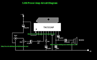
Simple 12V power AMP Circuit Using IC-TA222AP

Tags

Simple 12V power AMP Circuit Diagram

Simple 12V power AMP Circuit Using IC-TA222AP
Isuppose all car lowers will enjoy this circuit because at this moment when we are adapting to a vehicle amplifier also operates a major role.Today we you5.8W Power Amplifier Circuit Diagram.Here give we used Ic TA222AP.When you use a loudspeaker, you can use a speaker to the power amplifier.


Simple 12V power AMP Circuit Using IC-TA222AP


 TA7222AP pin out


PinNameDescription
1VccSupply Voltage
2RRRipple Reject
3MCMuting control
4OPAF Signal Input
5FBFB Filter
6GAGain adjust
7GNDGround
8GNDGround
9OPAF Output
10BSBootStrap

Night Lamp 120V Circuit Diagram

Tags

Night Lamp Circuit Diagram

Night Lamp 120V Circuit Diagram

Here we have introduced 120V circuit diagram with a little modification you can use the same circuit with 230.
When you build this circuit always try to use correct values Ac dangerous.If Because you are a child not try this circuit.
Night Lamp 120V Circuit Diagram

Note: Build this circuit on a p.c.b

12V to 230V Inverter with IRF 3205 Circuit Schematic with explanation

Tags

12V to 230V Inverter with IRF 3205


It is inverter circuit diagram.If you supplied 12v you can get 230V as the out put current.IRFZ44t loads up to 200W ,or 350W into IRFZ48 IRF3205 Can load up to  600W.When you build this circuit always try to use quality parts.And If you are a kid don't try this circuit diagram because 230V is dangerous.When you check this wear rubber gloves.


12V to 230V Inverter with IRF 3205 Circuit Schematic with explanation


Note : Don't try this alone.Because this circuit is very dangerous

230V Knight rider Circuit Diagram

Tags

230V Knight rider Circuit Diagram (modified)


 Note: Build this circuit on a pcb.
          Always supply 6V fro the circuit diagram

To see the general Knight rider circuit diagram click here

9-V Connection testor circuit Schematic using IC 741

Tags

Connection testor circuit diagram

9-V Connection testor circuit Schematic using IC 741


you will be able to guess whether the connections of the circuit is ok or not..Here we have used IC 741 .This circuit is operated with 9V power.


9-V Connection testor circuit Schematic using IC 741


Note : Build this circuit on a P.C.B

Simple LED Fader Circuit Diagram with explanation

Tags

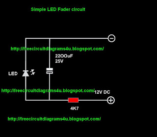
Simple LED Fader Circuit Diagram


this is a circuit for beginners.When we switch off the circuit it will take some time to switch off the light.After switching off the circuit the LED will get the power of capacitor.When the charge of the capacitor reducing we will be able to see like fading out the LED


Simple LED Fader Circuit Diagram with explanation

Note : Build this circuit on a pcb.

12V Battery level indicator Circuit Schematic With Explanation

Tags

12V Battery level indicator


According to the battery voltage LEDS will light up.


Note: #  To get maximum result build this circuit on a pcb.
          # Don't forget this is a 12V power circuit diagram

Simple LED Fader Circuit schematic Diagram with explanation for beginners

Tags

Simple LED Fader Circuit Diagram


this is a circuit for beginners.When we switch off the circuit it will take some time to switch off the light.After switching off the circuit the LED will get the power of capacitor.When the charge of the capacitor reducing we will be able to see like fading out the LED


Simple LED Fader Circuit schematic Diagram with explanation for beginners


Note : Build this circuit on a pcb.

230V LED Bulb circuit schematic with explanation


this is  230V LED  bulb circuit diagram.At the moment 230V LED bulbs have become very popular due to its low power consumption and due to it's clear light.I suppose this little circuit will be very useful circuit for you all.If you are an underage guy don't try this because 230V is so dangerous.


Note : Always use the correct values when you build this circuit
           Build this circuit on a PCB.

Advertisement