Showing posts with label Battery Charger. Show all posts

Mobile Phone and iPod Battery Charger Circuit project with schematic and explanation

Charge your iPod without connecting it to a computer!
Using the USB port on your computer to charge your player’s batteries is not always practical. What if you do not have a computer available at the time or if you do not want to power up a computer just for charging? Or what if you are traveling? Chargers for Mobile Phones iPods and MP3 players are available but they are expensive and you need separate models for charging at home and in the car.

This charger can be used virtually anywhere. While we call the unit a charger, it really is nothing more than a 5V supply that has a USB outlet. The actual charging circuit is incorporated within the iPOD or MP3 player itself, which only requires a 5V supply. As well as charging, this supply can run USB-powered accessories such as reading lights, fans and chargers, particularly for mobile phones.

The supply is housed in a small plastic case with a DC input socket at one end and a USB type "A" outlet at the other end, for connecting to Mobile Phone, an iPod or MP3 player when charging. A LED shows when power is available at the USB socket. Maximum current output is 660mA, more than adequate to run any USB-powered accessory.
Pictures, PCB and Circuit Diagram:
 Circuit_of_Mobile_Phone_Charger
Front View Of Mobile Phone and iPod Battery Charger Circuit

Circuit_of_Mobile_Phone_Charger1 
 Bottom View Of Mobile Phone and iPod Battery Charger Circuit
PCB of Mobile Phone Charger
PCB Layout Of Mobile Phone and iPod Battery Charger Circuit
Mobile Phone and iPod Battery Charger Circuit 
 Mobile Phone and iPod Battery Charger Circuit Diagram
PartsDescription
P11K
R11R-0.5W
R21R-0.5W
R31R-0.5W
R41K
R5560R
R610R-0.5W
R7470R
C1470uF-25V
C2100nF-63V
C3470pF
C4100uF-25V
D11N5404
D21N4001
D31N5819
D45.1V-1W Zener Diode
D55mm. Red LED
L1220uH
S1USB 'A' Type Socket
SW1On/Off Switch
IC1MC34063A
Specifications: 
Output voltage ----------------------5V 
Output current ---------------------660mA maximum for 5V out 
Input voltage range ------------------9.5V to 15V DC 
Input current requirement ----------500mA for 9V in, 350mA for >12V input 
Input current with output shorted--- 120mA at 9V in, 80mA at 15V in 
Output ripple ------------------------14mV (from no load to 660mA) 
Load regulation ----------------------25mV (from no load to 660mA) 
Line regulation ----------------------20mV change at full load from 9 to 18V input 
No load input current ----------------20mA 
(The specification for the computer USB 2.0 port requires the USB port to deliver up to 500mA at an output voltage between 5.25V and 4.375V).

The circuit is based around an MC34063 switch mode regulator. This has high efficiency so that there is very little heat produced inside the box, even when delivering its maximum output current. The circuit is more complicated than if we used a 7805 3-terminal regulator but since the input voltage could be 15V DC or more, the voltage dissipation in such a regulator could be 5W or more at 500mA. and 5W is far too much for a 7805, even with quite a large heatsink. Credit for this circuit goes to SiliconChip, A wonderful electronics magazine.

LM741 Using Dry Cell Battery Charger Circuit Circuit project explanation

This is Dry Cell Battery Charger Circuit. That can use charger battery get that about 12 hour. When apply to power supply 9 volt the equipment that fix in the circuit use for size battery AA. If use the size C or D should devalue of Resistor RX down be 68ohm and should not lead battery come to serial while voltage in cell battery lower 1.6V.
LM741 Using Dry Cell Battery Charger Circuit Diagram:
LM741 Using Dry Cell Battery Charger Circuit Circuit project  explanation 
The Comparator Circuit with (IC741) control Gate output from Pulse Oscillator at use the integrated circuit CMOS 4011 change Transistor that do infront charger battery until voltage tall 1.6V Comparator Circuit more make LED Flasher warn know for protect Charger battery expire. The next time is if friends have Dry Cell Battery that use be finished already , don’t abandon , try apply new again yes.

AUTOMATIC ENTRY BATTERY CHARGER 14-15 VOLT AC COURANTMAX 3 AMPERES

AUTOMATIC ENTRY BATTERY CHARGER 14-15 VOLT AC COURANTMAX 3 AMPERES


SCHEMA AUTOMATIC BATTERY CHARGER 14-15 VOLT AC CURRENT MAX 3A:


The assembly can achieve an excellent quality battery charger with which it is possible to recharge batteries from 1 to 2 volts car, and dry batteries of the systems used in alarm. Operation is completely automatic since, connect a battery, it will take office only if it is discharged, while it will automatically disconnect from the battery to be charged. The device is powered by a transformer whose secondary is 14-15 volts with a current of 3 Amperes minimum.


The adjustment trimmer TR1 is to have effectuede way, the output of the battery charger, a voltage of about 14.4 volts with no load. Distributable maximum current of 3 Amperes, it is therefore advised NOT to try recharging batteries with a capacity superieurede36Ah. Perfect use of this device is that of supplying a battery charger for alarm system with buffer battery.
During insertion, we must be very careful with connections to the battery respecting polarity AC.
For mounting of components , you must carefully follow the settlement scheme.
AUTOMATIC ENTRY BATTERY CHARGER 14-15 VOLT AC COURANTMAX 3 AMPERES


AUTOMATIC ENTRY BATTERY CHARGER 14-15 VOLT AC COURANTMAX 3 AMPERES

Circuit prints, AUTOMATIC ENTRY BATTERY CHARGER 14-15 VOLT AC COURANTMAX 3 AMPERES


LIST OF ELECTRONIC COMPONENTS: All resistors are of 1/4 watt unless statedotherwise. RL- 470 Ohms R2 = 10 ohms R3 = 270 Ohm TR1 = 10 ohms trimmer. Cl = 1000uF25Velec. DZ1 = 5.1 volts lWzener. T1 = 2N2218 T2 = 2N3055-BDW21C 1C1 = UA741 PT1 = KBL04 / 01 1 Support 8-pin. 1 Heat sink pourTl. 1 Heat sink pourT2.

SCHEMA BATTERY CHARGER Ni-Cd BATTERY AUTO circuit schematic with explanation

SCHEMA BATTERY CHARGER Ni-Cd BATTERY AUTO

SCHEMA BATTERY CHARGER Ni-Cd:
SCHEMA BATTERY CHARGER Ni-Cd BATTERY AUTO circuit schematic with explanation


It is a device that can charge any battery Ni-Cd between 4.8 and 1 4.4 Volts with a conventional car battery 1 2 volts. The charging current is constant it can be chosen from the values ​​1 50 20 mA by the selector S.
SCHEMA BATTERY CHARGER Ni-Cd BATTERY AUTO circuit schematic with explanation


This device is very useful for lovers of model making, the video operator, those who use small reception issuance of appliances and all those who use Ni-Cd batteries and need to recharge or network voltage n ' is not available.
SCHEMA BATTERY CHARGER Ni-Cd BATTERY AUTO circuit schematic with explanation


LIST OF ELECTRONIC COMPONENTS: All resistors are of 1/4 watt unless statedotherwise. R = 220Kohms R2 = 1 Kohm R3 = lKohm R4 = 120 ohm 1 watt R5 = 68 ohm 1 watt CI = 10 nF ceramic. C2 = 1000uF16Velec. C3 = 1000yF25Velec. D1 = 1N4001 ... 7 D2-1N4001 ... 7 D3-1N4001 ... 7 T1 = BDX53 T2 = BDX53 IC1 4047 = IC2 = 7805 1 selector 3 Heat Sinks 1 Support 14 pin

Simple battery charger with indicator Circuit schematic with explanation

This is a simple 12V rechargeable circuit smart battery charger circuit. You can use it to the best car battery charger circuit battery chargers, inverter battery charger, charger, etc. automatic emergency battery indicator alarm circuit also comes with the battery charger schematic. The main advantage of this indicator is a buzzer informs us when the battery needs recharging. This circuit diagram certainly contributes to your daily life battery charging applications. 
Battery charger diagram:
battery charger with indicator Circuit schematic with explanation

Electronic components: 
-Transformer (230V or 110V to 15V 15V 
T0)-bridge rectifier (1N4007 x 4) 
-condensateur (470uF, 50V) 
- Voltage regulator IC 7815 
-12V rechargeable battery how the circuit this battery charger - The load circuit is constructed. around IC 7815 voltage regulator and two transistors BC 548 - 230V or 110V The main is the first step down using a step down transformer and then it is filtered and rectifiered. - The DC voltage is supplied voltage regulation IC 7815 ;.the output will be regulated 15V 12V rechargeable battery is connected to the output of the voltage regulator. and charge when the main power is available. - When the battery voltage falls below a particular value LED1 stops glowing and buzzer gives her indicating that the battery is discharged and must be charged.

Single transistor based automatic battery charger circuit

Single transistor based automatic battery charger circuit

The following automatic battery-charger design is created with a circuit that could qualify as the simplest window comparator ever built around a single transistor. It starts charging when the battery voltage drops beyond a preset value, and it stops when an upper preset voltage is attained.

With the help of a precise variable voltage supply, the upper and lower voltage levels were set. The normally connected (NC) lead of the relay isn’t joined to the 15-V dc supply, which blocks this voltage from passing to the battery leads. This will accurately set the upper and lower levels. But the charging supply of 15 V dc was connected to the circuit.

First, the variable supply is fixed at 13.3 V dc—the voltage of a fully charged battery—and linked to the battery point of the circuit. The slider of VR1 is turned to the extreme end on the side that’s attached to the positive terminal of the battery. VR2′s slider should be turned toward the end that’s connected to VR1. The transistor turns on, shunting VR1. Then the slider of VR1 is turned toward the other extreme, which is the end connected to VR2.

The test supply voltage is now set to 11.8 V dc, which is the voltage of a drained battery. VR2 is then adjusted so that it just turns off the transistor again. The test voltage is raised to 13.3 V dc again, and VR1 is adjusted so that the transistor turns on. With the upper and lower levels set, the NC point is connected to the circuit (15-V dc charging voltage). Now the battery charger is set and ready to go.

S:/electronicdesign.com

simple circuit can be used to monitor whether a battery is charging or not

This simple circuit can be used to monitor whether a battery is charging or not. The voltage comparator IC LM393 is the heart of this circuit. The LED D1 will remain ON whenever there is at least 25 milli ampere current flowing to the battery. This particular circuit is designed for a 12V battery with charging current less than 1A.By slightly modifying the component values, the charging current and voltage can be modified.

simple circuit can be used to monitor whether a battery is charging or not

  • Assemble the circuit on a good quality PCB.
  • The IC1 must be mounted on a holder.
  • Do not use this circuit with batteries has more than 1A charging current.
S:circuitstoday.com

12V Ni-Cd battery charger

12V Ni-Cd battery charger
This circuit can be primarily used for charging 12V Ni-Cd battery packs. Any way 6V and 9V battery packs can be also charged by using this circuit a little compromise on power efficiency. The built in automatic current regulator regulates the charging current to somewhat 4 amperes. When the charging current reaches 4A, the voltage across resistor R1 becomes 0.7V and switches the transistor Q1 ON. The transistor Q2 which is now in ON state will shorts the base of Q3 to ground and inhibits the biasing of Q4 through which the charging is done. That is how the current regulation is achieved. When charging low voltage battery packs, the excess voltage will be dropped across Q4.It is advised to use a heat sink with transistor Q4.

  • The circuit can be assembled on a Vero board.
  • T1 can be a 230V primary, 12V secondary,4A step down transformer.
  • Bridge D1 can be made by using 1N5400 diodes.
  • Fuse F1 can be a 500mA type.
S:circuitstooday.com

ICLT4060 based Ni-MH battery charger

ICLT4060 based Ni-MH battery charger

This is the circuit diagram of a very powerful and efficient Ni-MH battery charger using IC LT4060 from Linear Technologies. In addition to Ni-MH batteries Ni-Cd batteries can be also charged by slightly modifying the circuit.For charging Ni-Cd batteries connect the CHEM pin (pin12) of the IC to +Vcc.Here the circuit is configured to charge 2 cells connected in series. By altering the connections of SEL0 and SEL1 pins, upto 4 batteries in series can be charged using this circuit. For charging a single cell, connect SEL0 and SEL1 pins to GND. For charging two cells, connect SEL1 to GND and SEL0 to Vcc. For charging three cells, connect SEL1 to VCC and SEL0 to GND. For charging 4 cells, connect SEL0 and SEL1 pins to VCC. The circuit also features temperature based charge qualification.An NTC thermistor connected at the NTC pin (pin11) of the IC serves as the temperature sensor.

Notes:

  • The circuit can be assembled on a Vero board.
  • Mount the IC on a holder.
  • Preset R2 must be set around 4K.
  • Type no of Q1 is not very critical. Any 3 to 5A PNP transistor will do the purpose.
  • LED D1 serves as a charge indicator.
S:circuitstoday.com

IC LM 317 based lead acid battery charger

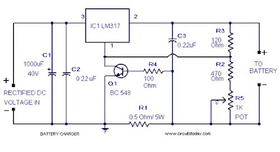
Here is a lead acid battery charger circuit using IC LM 317.The IC here provides the correct charging voltage for the battery.A battery must be charged with 1/10 its Ah value.This charging circuit is designed based on this fact.The charging current for the battery is controlled by Q1 ,R1,R4 and R5. Potentiometer R5 can be used to set the charging current.As the battery gets charged the the current through R1 increases .This changes the conduction of Q1.Since collector of Q1 is connected to adjust pin of IC LM 317 the voltage at the output of of LM 317 increases.When battery is fully charged charger circuit reduces the charging current and this mode is called trickle charging mode.

Battery Charger Circuit Diagram with Parts List.

IC LM 317 based lead acid battery charger

Notes .

  • Connect a battery to the circuit in series with a ammeter.Now adjust R5 to get the required charging current. Charging current = (1/10)*Ah value of battery.
  • Input to the IC must be at least 18V for getting proper charging voltage at the output .Take a look at the data sheet of LM 317 for better understanding.
  • Fix LM317 with a heat sink.


S:circuitstoday.com

description about simple car battery charger

This is Simple Car Battery Charger Electronic Suite. It consists of a transformer, a capacitor, an ammeter, and two diodes. To charge the battery, connect the (+) and (-) pole to the proper place in the battery. When the battery is not yet full, the ammeter reading is around 1-3 Amperes. If the ammeter is already full, the reading will show the value around 0. At this point, the battery should be removed from the circuit.

Note : BRX49 can also be change with 2N883, 2N891, or 2N6565.

This circuit is a full wave rectifier with two diodes. Capacitor is used to smoothen the output. However, the circuit will still be fully functioned without any capacitor because the battery itself is a capacitor. But if the circuit will be used as a 12 volt power supply, capacitor should be used.

description about simple car battery charger


S:electronicsuite.com

A very simple battery charger(based on IC L200)

This is Battery Charger using IC L200 Electronic Suite, A very simple battery charger circuit having reverse polarity indication is shown here. The circuit is based on IC L200.

L200 is a five pin variable voltage voltage regulator IC. The charging circuit can be fed by the DC voltage from a bridge rectifier or center tapped rectifier. Here the IC L200 keeps the charging voltage constant.

The charging current is controlled by the parallel combination of the resistors R2 & R3. The POT P1 can be used to adjust the charging current. This circuit is designed to charge a 12 V lead acid battery. The transistor t1, diode D3 and LED are used to make a battery reverse indicator. In case the battery is connected in reverse polarity ,the reverse polarity indicator red LED D5 glows. When the charging process is going on the battery charging indicator green LED D4 glows.

Notes

  • The circuit can be assembled on a good quality PCB or common board.
  • The values of R2 & R3 can be obtained from the equation, (R2//R3) =( V5-2)/(Io).

Where V5 is the charging voltage (voltage at pin 5) and Io is the charging current

The POT R8 can be used for fine adjustments of charging current.

  • If battery is connected in reverse polarity the RED LED will glow.
  • When the charging is going on the GREEN LED will glow.
  • The rectified input voltage to the charger can be 18V.

A very simple battery charger(based on IC L200)

S:http://www.circuitstoday.com

Simple battery charger circuit for car battery

This is a very simple battery charger for your car battery. The most expensive part of this circuit is a 5 A transformer. A car battery has very high value of electric current, so it's require battery charger with high electric current output.
Simple battery charger circuit diagram

12v battery monitor circuit based on lm3914


This bar graph LED battery level indicator circuit is based on LM3914 monolithic IC from National Semiconductor that senses the voltage levels of the battery and drives the 10 light emitting diodes based on the voltage level that is detected.


To calibrate the circuit it must be connected to an adjustable regulated power supply. Connect an input voltage of 15 volt between the positive and negative poles and adjust the 10K preset until Led 10 lights up. Lower the voltage and in sequence all other Led’s will light up. Check that Led 1 lights up at approximately 10 volts.

This circuit to your own needs by making small modifications. The circuits above is set for ‘DOT’ mode, meaning only one Led at a time will be lit. If you wish to use the ‘BAR’ mode, then connect pin 9 to the positive supply rail, but obviously with increased current consumption.

The LED brightness can be adjusted up- or down by choosing a different value for the 3K9 resistor connected at pin 6 and 7.

You can also change the to monitoring voltage level.

For example, let’s say you wanted to change to 12 – 15 volt, Remove the R2 resistor and connect 15volt to the input (+ and -) and adjust the 10K potentiometer until Led 10 lights up. Connect 200 Kilo-ohm potentiometer at pin 4 and -. Reconnect a voltage from 12 Volt to the input. Now adjust the 200K potentiometer until Led 1 lights up. When you are satisfied with the adjustment, feel free to exchange the 200K potentiometer with resistors again.(after measuring the resistance from the pot, obviously).


PARTS LIST
R156kΩ
R218kΩ
R33.9kΩ
VR110k Preset
D1 – D10LED
IC1LM3914


S:electonicecircuits.com

Portable devices used ni- cd auto battery charger


To use portable devices such as digital camera, wireless headphone, pocket radio, etc, which they operates with two "AAA" size batteries, using rechargeable Ni-Cd batteries is a conscionable way to reduce cost.

The circuit presented in the above schematic has been designed to charge automatically two series 350mAh "AAA" size batteries. Set the 20KOhms multiturn potentiometer to get a 2.78V on the 3rd pin of the LM311 which is a comparator. So if the net voltage of batteries reaches at 2.81V, the output of the LM311 goes high and then the state of the transistor becomes off, resulting in charging operation stops. When the red LED is lighted, it indicates that the charging is in the progress, and vice versa.

S:newcircuits.com

simple circuit makes it possible to monitor the charging process to a higher level(12 lead)


This simple circuit makes it possible to monitor the charging process to a higher level. Final adjustsments are simple and the only thing needed is a digital voltmeter for the necessary accuracy. Connect an input voltage of 12.65 volt between the positive and negative poles and adjust the 10K trimmer potentiometer until Led 10 lights up. Lower the voltage and in sequence all other Led's will light up. Check that Led 1 lights up at approximately 11.89 volts.

At 12.65 volt and higher the battery is fully charged, and at 11.89 is considered 'empty'. The green Led's indicate that the battery capacity is more than 50%, the yellow Led's indicate a capacity of 30% - 50% and the red Led's less that 30%. This circuit, with the components shown, uses less than 10mA. Ofcourse you can adapt this circuit to your own needs by making small modifications. The circuits above is set for 'DOT' mode, meaning only one Led at a time will be lit. If you wish to use the 'BAR' mode, then connect pin 9 to ground, but obviously with increased current consumption. The LED brightness can be adjusted up- or down by choosing a different value for the 4K7 resistor connected at pin 6/7 You can also change the to monitoring voltage level. For example, let's say you wanted to change to 10 - 13 volt, you connect 13volt to the input (+ and -) and adjust the 10K potentiometer until Led 10 lights up. Change temporarily the resistors at pin 4 with a 200 Kilo-ohm potentiometer and reconnect a voltage from 10 Volt to the input. Now, re-adjust the 200K potentiometer until Led 1 lights up. When you are satisfied with the adjustment, feel free to exchange the 200K potentiometer with resistors again.(after measuring the resistance from the pot, obviously).

The diode 1N4007 was included to protect the circuit from a wrong polarity connection. It is however strongly recommended to connect the monitor directly to the battery, in principle a connection to the cigarrette lighter would suffice but for reasons unknown at this time the voltage at that point is 0.2 volt lower than the voltage measured directly on the battery. Could be some residual resistance caused by ignition switch and path through the fuse?

S:newcircuits.com

Auto Battery Charger 12V circuit


This auto battery charger uses no transformer, rectifier, or filter capacitors on the schematic. No reason why you cannot add these. This charger will quickly and easily charge most any lead acid battery. The charger delivers full current until the current drawn by the battery falls to 150 mA. At this time, a lower voltage is applied to finish off and keep from over charging. When the battery is fully charged, the circuit switches off and lights a LED, telling you that the cycle has finished.

Auto Battery Charger Schematic

Auto Battery Charger Schematic

A heatsink will be needed for this auto battery charger ( U1.)

Auto Battery Charger Parts List
Resistor
R1 500 Ohm 1/4 W
R2 3K 1/4 W
R3 1K 1/4 W
R4 15 Ohm 1/4 W
R5 230 Ohm 1/4 W
R6 15K 1/4 W
R7 0.2 Ohm 10 W
Capacitor
C1 0.1uF 25V Ceramic
C2 1uF 25V Electrolytic
C3 1000pF 25V Ceramic
Diode
D1 1N457
Transistor
Q1 2N2905 PNP
Regulator
U1 LM350
Op Amp
U2 LM301A
S1 Normally Open Push Button Switch
MISC Wire, Board, Heatsink For U1, Case, Binding Posts or Alligator Clips For Output

To use the circuit, hook it up to a power supply/plug it in. Then, connect the battery to be charged to the output terminals. All you have to do now is push S1 (the “Start” switch), and wait for the circuit to finish.

DC Power Supply Schematic

C1 6800uF 25V Electrolytic Capacitor
T1 3A 15V Transformer
BR1 5A 50V Bridge Rectifier 10A 50V Bridge Rectifier
S1 5A SPST Switch
F1 4A 250V Fuse

If you want to use the auto battery charger without having to provide an external power supply, use above circuit. The first time you use the circuit, you should check up on it every once and a while to make sure that it is working properly and the battery is not being over charged.

Source: Car Battery Charger

6V at 1A Battery Charger Circuits with IC Regulator

battery charger circuit with IC regulator

battery charger circuit with IC regulator

The circuit is the elementary 6V 1A power supply circuit using IC regulator 7808. The 7808 three-terminal positive voltage regulator is available in the TO-220/D-PAK package build them useful in a wide range of applications.

The IC 7808 employs internal current limiting, thermal shut down and safe operating area protection, doing it essentially indestructible. If proper heat sinking is provided, it can deliver over 1 ampere output
current.

12v Battery Voltage Monitor circuit with LM339 comparator

voltage comparator circuit

voltage comparator circuit

In the circuit having a voltage quad comparator (LM339) is used as a simple bar graph meter to indicate the state of charge 12-volt lead-acid battery acid. A 5 volt reference voltage is in each of the (+) inputs of four comparators and the (-) inputs are connected, each point is connected to a voltage divider. The LED lights up when the voltage at the negative (-)-input exceeds the reference voltage. Calibration can be by adjusting the 2K potentiometer so that all four LEDs illuminate when the battery voltage is 12.7 volts indicates a full charge with no alrmcompload on the battery is done. At 11.7 volts, the LED should be made, and shows an empty battery. Each LED is a change of about 25% charge or 300 millivolts, so that 3 LEDs indicate 75%, 2 LEDs indicate 50%, etc.
The actual voltage on the temperature and battery type from, battery wet gel battery, etc . For more information on battery care.

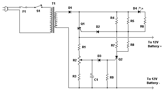
Automatic 12V Lead Acid Battery Charger


Parts

Part
Total Qty.
Description
Substitutions
R1, R32330 Ohm 1/4W Resistor
R21100 Ohm 1/4W Pot
R4, R5, R7, R8482 Ohm 2W Resistor
R61100 Ohm 1/4W Resistor
R911K 1/4W Resistor
C11220uF 25V Electrolytic Capacitor
D11P600 DiodeAny 50V 5A or greater rectifier diode
D211N4004 Diode1N4002, 1N4007
D315.6V Zener Diode
D41LED (Red, Green or Yellow)
Q11BT136 TRIAC
Q21BRX49 SCR
T1112V 4A TransformerSee Notes
F113A Fuse
S11SPST Switch, 120VAC 5A
MISC1Wire, Board, Heatsink For U1, Case, Binding Posts or Alligator Clips For Output, Fuse Holder


Notes

  1. R2 will have to be adjusted to set the proper finish charge voltage. Flooded and gel batteries are generally charged to 13.8V. If you are cycling the battery (AGM or gel) then 14.5V to 14.9V is generally recommended by battery manufacturers. To set up the charger, set the pot to midway, turn on the charger and then connect a battery to it's output. Monitor the charge with a voltmeter until the battery reaches the proper end voltage and then adjust the pot until the LED glows steadily. The charger has now been set. To charge multiple battery types you can mount the pot on the front of the case and have each position marked for the appropriate voltage.
  2. Q1 will need a heatsink. If the circuit is mounted in a case then a small fan might be necessary and can generally be powered right off the output of D1.
  3. T1 is a transformer with a primary voltage appropriate to your location (120V, 220V, etc.) and a secondary around 12V. Using a higher voltage secondary (16V-18V) will allow you to charge 16V batteries sometimes used in racing applications.
  4. If the circuit is powered off, the battery should be disconnected from it's output otherwise the circuit will drain the battery slowly.
source: aaroncake.net

Advertisement