Showing posts with label Radio. Show all posts

The principle of operation of radio transmitter circuit with explanation

The architecture of a transmitter varies greatly depending on the application, particularly as it is single frequency, as in broadcasting, as multifrequency radio, broadband as military communications, amateur radio, and depending on the modulation type.
The simplest single-frequency transmitter in amplitude modulation includes: a source at the carrier frequency, usually following a quartz oscillator; a power amplifier amplitude modulated by the amplified signal; an antenna coupled to the output of the amplifier.
The principle of operation of radio transmitter circuit with explanation


In broadcasting, the stages of low level, or "signal stages" comprising oscillator, modulator, filter, or generate the modulated carrier signal to a power of a few watts.
They are called excited. The power amplifier following is sometimes simply called "issuer".
Radiotelephone HF, VHF or UHF band, the need for selection of channel or frequency can lead to a frequency changing architecture similar to that of a receptor, for modulating and filter at a fixed frequency.
Radar power, the simplest scheme is a type of self-magnetron oscillator replaced by amplifiers for radar signal processing.
Source: wikipedia.org | CC

2Km Fm Transmitter Shematic diagram with Explanation Circuit


2Km Fm Transmitter Shematic diagram with Explanation Circuit
This is a powerful transmitter so first of all I would like to tell you not to use this for illeagl things.You can transmitt signals from 2km.Use a matching antenna for this.


2Km Fm Transmitter Shematic diagram with Explanation Circuit


Note

# Don't give power without an antenna
# For L1 make 3 turns of 1mm enamelled copper wire on a 10mm diameter plastic former. On the same core make 2 turns of 1 mm enamelled copper wire close to L3 and that will be L2.
# by using R9 the gain can be controlled
# Inductor L3 can be a VK220J type RFC.
# This circuit operates with 9V to 18V ( Dont pass 24V)

Simple FM Transmitter Circuit Schematic With explanation

Simple FM Transmitter Circuit Schematic With explanation

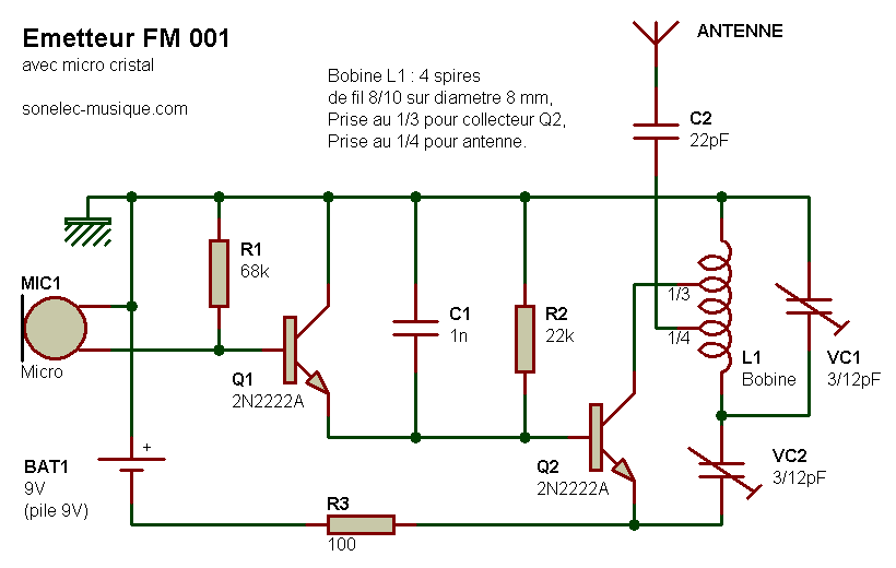
This circuit uses a small microphone to capture the sound and some transistors to generate radio waves that can be picked up by a FM receiver like a car stereo.How it works:
From left to right, the first part is the microphone and some resistors to get it working. Next we have a capacitor and the first transistor, this amplifies the sound from the microphone so that it can be loud enough to work with. The last part, there is a transistor, a coil and some capacitors. This part generates the radio waves and combines them with the sound from the mic to transmit it thru the antenna.
The coil is made with about 9 turns of wire, use a pencil to get the right diameter for the coil. The capacitor with the arrow is called a trimmer capacitor, it has a small screw to adjust the value, we'll use it to tune a certain frequency or station to transmit on.
simple fm radio transmitter
Simple FM Transmitter Circuit Schematic With explanation

(click to enlarge)

AM receiver Circuit Schematic With Explnation


Here is a low cost AM receiver circuit that can be tuned from around 550 to 1100 KHz. Three transistors are used in this project. The transistors Q1 and Q2 are wired as a compound transistor pair in which Q1 is an emitter follower and Q2 is a common emitter amplifier. The emitter follower prevents the loading of tank circuit, while the common emitter amplifier necessary voltage gain. The L1 and C2 forms the tank circuit.The L1 also does the job of antenna.The series combination of R6 and R7 gives a regenerative feedback between output of the Q2 and tank circuit. The transistor Q3 performs the demodulation of the carrier signal. It also provides amplification the demodulated signal. The audio output is coupled out from the collector of Q3 via the capacitor C3.Capacitor C6 provides some noise filtering.

Circuit Schematic With Explnation


Notes.

* The circuit can be assembled on a general purpose PCB.
* Use a 9V PP3 battery for powering the circuit.
* R7 can be used to adjust the sensitivity and selectivity of the circuit.
* A high impedance head phone can be used for listening the radio.
* For L1 make 60 turns of 26 SWG enameled copper wire on a 3/8 inch diameter, 3inch long ferrite rod.
* The moving plates of C2 must be connected to the base of Q1 and fixed plates must be connected to the junction of C3 and R6.Reversing the connection may decrease the stability.

single-chip AM radio integrated circuit(low cast)


The ZN414 is a low cost, single-chip AM radio integrated circuit. Launched in 1972, the part was designed and supplied by Ferranti.
The ZN414 was popular amongst hobbyists as a fully working AM radio could be made with just a few external components, a crystal earpiece and a 1.5 V cell.
The manufacturing process for the ZN414 chip used a relatively new (for the time) technique known as Collector Diffusion Isolation (CDI). CDI was invented by engineers at Bell Telephone Laboratories and subsequently developed into a commercial process by Ferranti in the UK.
The original ZN41x family have equivalents to the original 3-pin ZN414 are available, with part codes of MK484, TA7642 and (mainly in India, the Far East & Australasia) YS414 and LMF501T. Note that on the YS414 part, pins 1 (output) and 3 (ground/earth) are transposed.

Notes:
This is circuit design around the popular ZN414 I.C. this receiver covers the AM band from 550 - 1600 KHz values. For Long wave the coil needs to be changed. Use one from an old MW radio to save time.
The ZN414 is a tuned radio frequency designed and incorporates several RF stages and an AM detector. It is easily overloaded and the operating voltage is critical to achieve good results.
The two 1N4148 diodes both supply 1,2Volt (0,6 Volt each).
The ZN414 is variable from 0 to 1.8volts DC. If you live in an area that is permeated with strong radio signals, then the voltage will need to be decreased. I found optimum performance with a supply of around 1.2 volts.
The audio amplifier is built around an LM386 op-amp. The voltage gain of the complete audio amplifier is around 15. The audio output of the complete receiver is really good and quite free from distortion.
The coil needs approximately 55 turns of 0.315 (30 SWG) of enamelled copper wire on a 100 x 10mm ferrite rod. A process of trial and error will help you achieve the optimum number of windings.
Parts:
R1 = 100K
R2 = 1.5K
R3 = 1.5K
R4 = 470R
R5 = 10R

C1 = 0.01mF
C2 = 0.1mF
C3 = 1mF
C4 = 0.02mF
C5 = 0.05mF
C6 = 220mF
C7 = 220mF
C8 = 10mF

D1 = 1N4148
D2 = 1N4148

VR1 = 5K LOG
VC1 = 3 – 500pF variable

U1 = LM386
U2 = ZN414 or MK484 or TA7642 or LMF501T

single-chip AM radio integrated circuit(low cast)

single-chip AM radio integrated circuit(low cast)

The ZN414 is a low cost, single-chip AM radio integrated circuit. Launched in 1972, the part was designed and supplied by Ferranti.
The ZN414 was popular amongst hobbyists as a fully working AM radio could be made with just a few external components, a crystal earpiece and a 1.5 V cell.
The manufacturing process for the ZN414 chip used a relatively new (for the time) technique known as Collector Diffusion Isolation (CDI). CDI was invented by engineers at Bell Telephone Laboratories and subsequently developed into a commercial process by Ferranti in the UK.
The original ZN41x family have equivalents to the original 3-pin ZN414 are available, with part codes of MK484, TA7642 and (mainly in India, the Far East & Australasia) YS414 and LMF501T. Note that on the YS414 part, pins 1 (output) and 3 (ground/earth) are transposed.

Notes:
This is circuit design around the popular ZN414 I.C. this receiver covers the AM band from 550 - 1600 KHz values. For Long wave the coil needs to be changed. Use one from an old MW radio to save time.
The ZN414 is a tuned radio frequency designed and incorporates several RF stages and an AM detector. It is easily overloaded and the operating voltage is critical to achieve good results.
The two 1N4148 diodes both supply 1,2Volt (0,6 Volt each).
The ZN414 is variable from 0 to 1.8volts DC. If you live in an area that is permeated with strong radio signals, then the voltage will need to be decreased. I found optimum performance with a supply of around 1.2 volts.
The audio amplifier is built around an LM386 op-amp. The voltage gain of the complete audio amplifier is around 15. The audio output of the complete receiver is really good and quite free from distortion.
The coil needs approximately 55 turns of 0.315 (30 SWG) of enamelled copper wire on a 100 x 10mm ferrite rod. A process of trial and error will help you achieve the optimum number of windings.
Parts:
R1 = 100K
R2 = 1.5K
R3 = 1.5K
R4 = 470R
R5 = 10R

C1 = 0.01mF
C2 = 0.1mF
C3 = 1mF
C4 = 0.02mF
C5 = 0.05mF
C6 = 220mF
C7 = 220mF
C8 = 10mF

D1 = 1N4148
D2 = 1N4148

VR1 = 5K LOG
VC1 = 3 – 500pF variable

U1 = LM386
U2 = ZN414 or MK484 or TA7642 or LMF501T
S:elec-circuits.blogspot.com

How to make foxhole radio receiver (with no batteries) Foxhole radio receiver or Crystal receiver is a form of radio that does not operate on local

How to make foxhole radio receiver (with no batteries)

Foxhole radio receiver or Crystal receiver is a form of radio that does not operate on local oscillator, which makes it hard to be detected by other electronic device. One of the most interesting thing of Foxhole radio is that it could be operated without the use of batteries, as it is powered solely by the radio waves through its long wire antenna.

Foxhole radio was (supposedly) popular during World War II because it enabled the GI to receive radio broadcast in the middle of the war, particularly in France as the Germans has outlawed the use of radio by civilians, thus the American GI need to build their own receiver to receive broadcasts. Typical component of foxhole radio during those days are : a period razor blade (not the newer galvanized one), carbon (obtained from pencil) and some copper wire with woodblock or cardboard as its base.

http://please.name.my/302/how-to-make-foxhole-radio-receiver-with-no-batteries.html

No need electricity for radio only one transister

Experts And amateurs have been Experimenting with radios without batteries since the wireless communication started.
In many designs we've seen radios that operate without power, but all are known to use the diode 1N34. (Crystal Radio).
Although significant improvements have increased the sensitivity and selectivity of these system circuits, Performances were limited until new techniques have emerged.
Here we have the first transistor radio that works without batteries, it is powered by random electric fields are everywhere in the atmosphere.
These circuits are relatively cheap to manufacture, have more volume and better reception from the crystal radios.
This circuit is a medium wave receiver and attaches easily to frequencies from 500Khz to 11Mhz.
To get good results in the reception of radio stations, we should give great importance to the ground and the antenna.
To listen to distant and weak stations we have to use a battery 9volt parallel with the capacitor C4 with it's positive side between R2 and C4.

The coils are in the frequency of 500-1500Khz is tight and closely wrapped.

The coils are in frequency of 1.5-11Mhz is more tighter and more closely wrapped

monolithic ic KA22429 based one chip FM radio

The KA22429 is a monolithic integrated circuit designed for Portable FM radio.
It is consistng of RF input stage, Mixer, IF, Mute control and Loop (earphone drive) AMP.
It is suitable a pocket - size radio.

FEATURES

  • Minimum number of external parts required
  • It is able to a single trimmer tuning
  • No FM det coil
  • It is FLL detect system (76KHz)
  • Operating voltage: Vcc= 1.8V~6.v

simple circuit of an FM booster with component list


Here is a simple circuit of an FM booster that can be used to listen to programmes from distant FM stations clearly. This amplifier will pull in all distant FM stations clearly. The circuit is configured as a common-emitter tuned RF pre-amplifier wired around VHF/UHF transistor Q1.

rangkaian boster radio penerima FM
Skema rangkaian boster radio penerima FM


2SC2570. (Only C2570 is annotated on the transistor body.) Assemble the circuit on a good-quality PCB (preferably, glass-epoxy). Adjust input/ output trimmers (VC1/VC2) for maximum gain.

All capacitors are ceramic and 50V is the standard but the 25V types work fine too. Trimmer capacitors Tr1 and Tr2 (22pF) are adjusted for maximum gain. Input coil L1 consists of 4 turns of 20SWG enamelled copper wire over a 5mm diameter former. It is tapped at the first turn from the ground lead side. Coil L2 is similar to L1, but has only three turns. Pin configuration is shown in the diagram.


Component List:
  • R1 = 27K
  • R2 = 270 ohm
  • R3 = 1K
  • Tr1,Tr2 = 22pF, trimmer cap (15-40pF)
  • C1,C2 = 5.6pF
  • C3 = 0.001uF (1nF), ceramic
  • C4,C5 = 10pF, ceramic
  • C6 = 0.1uF (100nF), ceramic
  • Q1 = 2SC2498, 2SC2570, 2N5179, SK9139, or NTE10. NPN VHF/UHF transistor
  • L1 = 4 turns of 20SWG magnet wire, 5mm diameter. (so-called 3T+1)
  • L2 = 3 turns of 20SWG magnet wire, 5mm diameter.

only five parts containing crystal radio circuit


Part
Total Qty.
Description
Substitutions
C11Tuning Capacitor (See Notes)
D111N34 Germanium Diode
L11Loopstick Antenna (See Notes)
SPKR11Crystal Earphone
MISC1Wire, Board, Wire For Antenna, Knob For C1


  1. C1 and L1 can be bought, or salvaged from an old AM radio (which is where I got mine). You may need to experiment with the connections on L1 in order to get the best (or any) signal.
  2. You may or may not need the ground connection. I never use it and the radio usually works fine without it.
  3. The bigger the antenna, the more stations you pick up and the louder you hear them. On my radio, I get about 10 stations, 3 of which are very loud in the earphone. Of course, not everyone has room for a 60' antenna...
  4. A 47K resistor in parallel with the earphone will help properly load the detector .

S:www.aaroncake.net/circuits

advance aircraft radio communication receiver


The communications between commercial aircraft and the ground can be interesting, amusing and sometimes even disturbing. However radios that receive the approximately 220MHz to 400MHz band commonly used for aircraft (both military and commercial) are not easily found. And scanners can be complicated, large and expensive. With an easy to build circuit such as this one, everyone can enjoy listening in on these conversations.

Schematic


Parts

Part
Total Qty.
Description
Substitutions
R1, R3247K 1/4W Resistor
R2110K 1/4W Resistor
R414.7K 1/4W Resistor
R515K Linear Taper Pot
R612.2K 1/4W Resistor
C1, C2, C3, C640.001uF Ceramic Disc Capacitor
C412.2pF Ceramic Disc Capacitor
C511pF Ceramic Disc Capacitor
C7115uF 15V Electrolytic Capacitor
C8118pF Variable Capacitor
D111N82 Diode
Q112N918 NPN Transistor
L11See Notes
L211.8uH Inductor
ANT11Approx. 18 Inch Wire Antenna
MISC1PC Board, Wire, Knob For C8

Notes

  1. The circuit originally appeared in the Think Tank column of the Sept. 1995 issue of Popular Electronics.
  2. L1 is made by winding 2 turns of 22 AWG magnet wire on a 5/32 drill bit. This inductor can be modified to shift the frequency range of the circuit.
  3. The antenna can also be placed at the anode of D1 if overload is a problem with it connected to the emitter of Q1
  4. R5 adjusts regen and thus sensitivity.


Lower Sensitivity Pocket FM Radio BF184


The idea was to use a simple receiver, but can be used to escape to 3 times viewed. My previous 6-transistor receiver was more complicated and requires 12 volts. This means that 10 AA batteries. I designed and built acircuit board, and built a small aluminum box will hold Comact as possible.

There is nothing wrong with this design. The detector has a simple Colpitts oscillator is of a type often used in other receptor super-regeneration. It’s natural for yourself. The sensitivity for this type of detector is relatively low, but it’s simple and easy to get work. As always, gave me a feedback control to determine the optimum point of operation, ie. maximum sensitivity and minimum SCA / stereo subcarrier beat.

REF:www.stardi.com/simple-fm-receiver-pocket-fm-radio-circuit-main-bf184-transistor/

No Power Supply Requires to Operate for Emergency Crystal Radio

Crystal Radio

Emergency Crystal radio
requires no power supply to operate because it uses energy from the signals it receives. Performance is – like one should expect – poor. Nevertheless, with a good antenna and proper ground, it shouldn’t be too difficult to tune to a strong AM station.


While this emergency crystal radio circuit is very simple, many points should be observed. The variable capacitor is relatively hard to get in a store these days, so your best bet to find one could be a junked AM receiver. Connect the case to the antenna and the central rod to ground. Otherwise, you’ll de-tune the circuit every time you touch the capacitor.

Next comes the coil. Originally, 60-80 turn air core coils of large diameter (10cm) were used. A less bulky alternative could be 30 turns of enamel-coated magnet wire wound on a ferrite rod. It works for me, at least.

Detection and demodulation of the signal is done by a germanium diode. In the US, 1N34 seems to be very popular. Here in Europe, AA119 is more common and offers similar performance.

Finally, you’ll need high-impedance headphones. These are also quite rare. Ordinary Walkman phones won’t work directly. Add an audio output transformer to drive them or build a small amplifier like shown on the next page.

Problems:
To hear anything, you’ll need a very long antenna. Use any hookup wire at least a few meters in length. Make sure that no power lines are nearby! A good ground is also vital, like a cold water pipe. Otherwise, plant a metal rod as deeply in the ground as possible and it should work well.

Possible uses:
In these times of incredible advance in technology, such a simplistic receiver doesn’t seem to have any real use at all. It’s a nice project for the more nostalgic types, though. Since no power is required for operation, having such a receiver could prove handy in an emergency situation or just to hear the news when you’re out in the woods backpacking

Build a Dipole FM antenna

The antenna rod is made of 6 mm copper tube I found in a shop for cars. It is actually tubes for the breaks, but the tube works great as antenna rods. You can use all kinds of tubes or wire. The benefit of using a tube, is that it is strong and the wider tube diameter you use, the wider frequency range (bandwidth) you will also get. I have noticed that the transmitter gives highest output power around 104-108 MHz so I set my transmitter to 106 MHz.

Dipole-FM-Antenna-Diagram

The calculation gave the rod length of 67 cm. So I cut off two rods at 67cm each. I also found plastic tube to hold the rods and to give it a more stable construction. I use one plastic tube as boom and a second to contain the two rods. You can see how I used black duct tape to hold the two tubes together. Inside the vertical tube are the two rods and I have connected a coax to the two rods. The coax is twisted 10 turns around the horizontal tube to form a balun (rf choke) to prevent reflections. This is a poor mans balun and lot of improvement can be done here.

Copper Material

Copper Material

I placed the antenna on my balcony and connected it to the transmitter and turned on power supply. I live in a medium city so I took my car and drove away to test the performance. The signal was perfect with crystal clear stereo audio. There are many concrete building around my transmitter which affects the transmitting range. The transmitter worked up to 5 km distance when the sight was clear (could not obtain line-in-sight). In city environment it reached 1-2km, due to heavy concrete.

Dipole FM Antenna Construction

Dipole FM Antenna Construction

I find this performance very good for a 1 W amplifier with an antenna which took me 45 min to build. One should also take in account that the FM signal is Wide FM, which consume much more energy than a narrow FM signal does. All together, I was very pleased with the result.

Antenna Testing and Measuring
Thanks to a complex antenna analyser, I have been able to get a plot of the antenna performance.
The red curve show the SWR and the grey show Z (impedance). What we want is a SWR of 1 and Z to be close match to 50 ohm.

As you can see, the best match for this antenna is at 102 MHz where we have SWR = 1.13 and Z = 53 ohm. I did run my antenna at 106 MHz, where the match is worse SWR = 1.56 and Z = 32 ohm.

Conclusion: My antenna was not perfect for 106 MHz, I should re-run my filed test at 102 MHz. I will probably get better results and longer transmitting distance. Or I should make the antenna a bit shorter to match the frequency 106 MHz.

Browse: FM Antenna Outdoor on Amazon

See more: Wireless FM Transmitter

Source: How to build a dipole antenna in 45 minutes

How to Build a Dipole FM antenna

The antenna rod is made of 6 mm copper tube I found in a shop for cars. It is actually tubes for the breaks, but the tube works great as antenna rods. You can use all kinds of tubes or wire. The benefit of using a tube, is that it is strong and the wider tube diameter you use, the wider frequency range (bandwidth) you will also get. I have noticed that the transmitter gives highest output power around 104-108 MHz so I set my transmitter to 106 MHz.

Dipole-FM-Antenna-Diagram

The calculation gave the rod length of 67 cm. So I cut off two rods at 67cm each. I also found plastic tube to hold the rods and to give it a more stable construction. I use one plastic tube as boom and a second to contain the two rods. You can see how I used black duct tape to hold the two tubes together. Inside the vertical tube are the two rods and I have connected a coax to the two rods. The coax is twisted 10 turns around the horizontal tube to form a balun (rf choke) to prevent reflections. This is a poor mans balun and lot of improvement can be done here.

Copper Material

Copper Material

I placed the antenna on my balcony and connected it to the transmitter and turned on power supply. I live in a medium city so I took my car and drove away to test the performance. The signal was perfect with crystal clear stereo audio. There are many concrete building around my transmitter which affects the transmitting range. The transmitter worked up to 5 km distance when the sight was clear (could not obtain line-in-sight). In city environment it reached 1-2km, due to heavy concrete.

Dipole FM Antenna Construction

Dipole FM Antenna Construction

I find this performance very good for a 1 W amplifier with an antenna which took me 45 min to build. One should also take in account that the FM signal is Wide FM, which consume much more energy than a narrow FM signal does. All together, I was very pleased with the result.

Antenna Testing and Measuring
Thanks to a complex antenna analyser, I have been able to get a plot of the antenna performance.
The red curve show the SWR and the grey show Z (impedance). What we want is a SWR of 1 and Z to be close match to 50 ohm.

As you can see, the best match for this antenna is at 102 MHz where we have SWR = 1.13 and Z = 53 ohm. I did run my antenna at 106 MHz, where the match is worse SWR = 1.56 and Z = 32 ohm.

Conclusion: My antenna was not perfect for 106 MHz, I should re-run my filed test at 102 MHz. I will probably get better results and longer transmitting distance. Or I should make the antenna a bit shorter to match the frequency 106 MHz.

Browse: FM Antenna Outdoor on Amazon

See more: Wireless FM Transmitter

Source: How to build a dipole antenna in 45 minutes

Radio Wave Alarm 4093 CMOS IC

This very simple alarm circuit is sure to have the police beating a path to your door - however, it has the added advantage of alerting you to their presence even before their footsteps fall on the doormat.


The alarm circuit transmits on MW (Medium Wave) (this is the small problem with the police). IC1a, together with a sensor (try a 20cm x 20cm sheet of tin foil) oscillates at just over 1MHz. This is modulated by an audio frequency (a continuous beep) produced by 4093 CMOS IC1b. When a hand or a foot approaches the sensor, the frequency of the transmitter (CMOS IC1a) drops appreciably.

Suppose now that the alarm circuit transmits at 1MHz. Suppose also that your radio is tuned to a frequency just below this. The 1MHz transmission will therefore not be heard by the radio. But bring a hand or a foot near to the sensor, and the transmitter's frequency will drop, and a beep will be heard from the radio.

More for RF Alarm

AM FM Simultaneous Transmitter Using Digital IC

AM FM Simultaneous Transmitter Using Digital IC

Double Side Band AM Transmitter Circuit

The circuit of AM transmitter is designed to transmit (amplitude modulated) DSB (double side band) signals. A modulated AM signal consists of a carrier and two symetrically spaced side bands. The two side bands have the same amplitude and carry the same information. In fact, the carrier itself coveys or carries no information. In a 100% modulated AM signal 2/3 rd of the power is wasted in the carrier and only 1/6th of the power is contained in each side band.

In this transmitter we remove the carrier and transmitt only the two side bands. The effective output of the circuit is three times that of an equivalent AM transmitter.

Op Amp IC741 is used here as a microphone amplifier to amplify the voice picked up by the condenser microphone. The output of the op amp is fed to the double balanced modulator (DBM) build around four IN4148 diodes. The modulation level can be adjusted with the help of preset VR1.

The carrier is generated using crystal oscillator wired around BC548 transistor T2. The carrier is further amplified by transistor T1, which also acts as a buffer between carrier oscillator and the balanced modulator. The working frequency of the transmitter can be changed by using crystals of different frequencies. For multi frequency operation, selection of different crystals can be made using a selector switch.

Ths output of the DBM contains only the product (of audio and carrier) frequencies. The DBM suppresses both the input signals and produces double side band suppressed carrier (DSBSC) at its output. However, since the diodes used in the balanced modulator are not fully matched, the output of the DBM does contain some residual carrier. This is known as carrier leakage. By adjusting the 100 ohm preset VR2 and trimmer C7 you can null the carrier leakage.

To receive DSB signals you need a beat frequency oscillator to reinsert the missing carrier. If you don’t have a beat frequency oscillator, or want to transmitt only AM signal, adjust preset VR2 to leak some carrier so that you can receive the signals on any ordinary radio receiver. In AM mode 100% modulation can be attained by adjusting preset VR1 and VR2.

The DSBSC signal available at the output of the balanced modulator is amplified by two stages of RF linear amplifiers. Transistor 2N2222A (T3) is used as an RF pre amplifier, which provides enough signal amplification to drive the final power amplifier build around transistor SL100B. The output of the final power amplifier is connected to the antenna.

All coils are to be wound ferrite balun core (same as used in TV balun transformer of size 1.4 cm * 0.6 cm) using 24 swg enameled copper wire. Proper heat sink should be provided for SL100B transistor used as final power amplifier.

AM DSB Transmitter

X1 – 8+8 Turns Bifalar 24 SWG On TV Balune Core
X2 – Primary 12 Turns, Secondary 4 Turns. 24 SWG on TV Balun Core (dot indicates start of coil).
X3 – 20 Turns 24 SWG on TV Balun Core

Range of the circuit depends on the type of antenna used. It is very important to use matched antenna to radiate the signals effectively. I used horizontal dipole antenna, which is simple and easy to construct. For 7 MHz, ie 40 meter ham band the length of dipole antenna will be 20 meter. Use 75 Ohms co-axial cable to connect antenna and transmitter. I was able to get 57 report from station 80 kilometer away. You can easily add a Linear RF amplifier using IRF830 to get more power.

Micro Power AM Broadcast Transmitter Schematic

Micro Power AM Broadcast Transmitter


In this circuit, a 74HC14 hex Schmitt trigger inverter is used as a square wave oscillator to drive a small signal transistor in a class C amplifier configuration. The oscillator frequency can be either fixed by a crystal or made adjustable (VFO) with a capacitor/resistor combination. A 100pF capacitor is used in place of the crystal for VFO operation. Amplitude modulation is accomplished with a second transistor that controls the DC voltage to the output stage. The modulator stage is biased so that half the supply voltage or 6 volts is applied to the output stage with no modulation. The output stage is tuned and matched to the antenna with a standard variable 30-365 pF capacitor. Approximately 20 milliamps of current will flow in the antenna lead (at frequencies near the top of the band) when the output stage is optimally tuned to the oscillator frequency. A small ‘grain of wheat’ lamp is used to indicate antenna current and optimum settings. The 140 uH inductor was made using a 2 inch length of 7/8 inch (OD) PVC pipe wound with 120 turns of #28 copper wire. Best performance is obtained near the high end of the broadcast band (1.6 MHz) since the antenna length is only a very small fraction of a wavelength. Input power to the amplifier is less than 100 milliwatts and antenna length is 3 meters or less which complies with FCC rules. Output power is somewhere in the 40 microwatt range and the signal can be heard approximately 80 feet. Radiated power output can be approximated by working out the antenna radiation resistance and multiplying by the antenna current squared. The radiation resistance for a dipole antenna less than 1/4 wavelength is

R = 80*[(pi)^2]*[(Length/wavelength)^2]*(a factor depending on the form of the current distribution) The factor depending on the current distribution turns out to be [(average current along the rod)/(feed current)]^2 for short rods, which is 1/4 for a linearly-tapered current distribution falling to zero at the ends. Even if the rods are capped with plates, this factor cannot be larger than 1. Substituting values for a 9.8 foot dipole at a frequency of 1.6 MHz we get R= 790*.000354*.25 = .07 Ohms. And the resistance will be only half as much for a monopole or 0.035 Ohms. Radiated power at 20 milliamps works out to about I^2 * R = 14 microwatts.

am transmitter schematic, 1 WATT AM AUDIO TRANSMITTER, 1 WATT FM TRANSMITTER SCHEMATIC, diagram of current wavelength used in micro current, digital fm transmitter schematic, gambar rangkaian radio broadcasting, half watt AM transmitter transmitter, micro broadcasting mw, micro power FM transiver, mosfet am broadcast

Advertisement