Showing posts with label Radio Transmission. Show all posts

The principle of operation of radio transmitter circuit with explanation

The architecture of a transmitter varies greatly depending on the application, particularly as it is single frequency, as in broadcasting, as multifrequency radio, broadband as military communications, amateur radio, and depending on the modulation type.
The simplest single-frequency transmitter in amplitude modulation includes: a source at the carrier frequency, usually following a quartz oscillator; a power amplifier amplitude modulated by the amplified signal; an antenna coupled to the output of the amplifier.
The principle of operation of radio transmitter circuit with explanation


In broadcasting, the stages of low level, or "signal stages" comprising oscillator, modulator, filter, or generate the modulated carrier signal to a power of a few watts.
They are called excited. The power amplifier following is sometimes simply called "issuer".
Radiotelephone HF, VHF or UHF band, the need for selection of channel or frequency can lead to a frequency changing architecture similar to that of a receptor, for modulating and filter at a fixed frequency.
Radar power, the simplest scheme is a type of self-magnetron oscillator replaced by amplifiers for radar signal processing.
Source: wikipedia.org | CC

2Km Fm Transmitter Shematic diagram with Explanation Circuit


2Km Fm Transmitter Shematic diagram with Explanation Circuit
This is a powerful transmitter so first of all I would like to tell you not to use this for illeagl things.You can transmitt signals from 2km.Use a matching antenna for this.


2Km Fm Transmitter Shematic diagram with Explanation Circuit


Note

# Don't give power without an antenna
# For L1 make 3 turns of 1mm enamelled copper wire on a 10mm diameter plastic former. On the same core make 2 turns of 1 mm enamelled copper wire close to L3 and that will be L2.
# by using R9 the gain can be controlled
# Inductor L3 can be a VK220J type RFC.
# This circuit operates with 9V to 18V ( Dont pass 24V)

Simple Light Audio Transmitter Circuit Schematic Diagram with explanation

This is the Simple Light Audio Transmitter Circuit Diagram. In the visible-light transmitter, a 7805 voltage regulator is connected in a variable-voltage configuration, and an audio signal is fed to the common input, to modulate the output voltage. The modulated output voltage is used to transmit intelligence via an incandescent lamp.
Simple Light Audio Transmitter Circuit Schematic Diagram with explanation


Simple Light Audio Transmitter Circuit Schematic Diagram with explanation

Transmitter construction

The oscillator is the heart of the transmitter. It has four leads, but we only use three of them. When the power is connected to two of the leads, the voltage on third lead starts jumping between 0 volts and 5 volts, one million times each second.

The oscillator is built into a metal can. The corners of the can are rounded, except for the lower left corner, which is sharp. This indicates the where the unused lead is. The lead is there to help hold the can down firmly on the printed circuit board, but it is not connected to anything inside the can.

The other main part is the audio transformer . In this circuit it is used as a modulator. The modulator changes the strength of the radio waves to match the loudness of the music or voice we want to transmit.

A pictorial diagram of the transmitter looks like this:

Transmitter construction


A photograph of the completed transmitter is shown below:

Transmitter construction


The transformer has two leads on one side, (red and white in the photo ) and three leads on the other side (blue, black and green in the photo). The two leads are the low impedance side of the transformer, (the 8 ohm side). The three leads are the high impedance side (the 1000 ohm side). The middle of the three leads is called the center tap, and we won't be using it in this circuit.

To get the best range, we put the low impedance side of the transformer in series with the oscillator. This means that the signal source must be capable of driving heavy loads, like an 8 ohm speaker.

If you are trying to use a weaker signal source, such as an iPod or some other MP3 player that can only drive 32 ohm earphones, you will want to reverse the transformer, so that the 1,000 ohm side is in series with the oscillator, and the 8 ohm side is connected to your signal source. You will get slightle less range, but your odds of getting some modulation of the signal will be much better.

S:sci-toys.com

features of mini fm radio transmitter circuit


This is a mini fm Radio transmitter circuit. The supply voltage is between 1.1 – 3 Volts with power consumption is 1.8 mA at 1.5 Volts. This circuit should be able to cover 30 meters of range max. at 1.5 Volts.

mini FM transmitterSkema rangkaian mini FM transmitter


Note:
* Use a battery for powering the circuit.It will reduce noise.
* An FM antenna from a old radio is a better option than the wire antenna.


PN2222A transistor description

This device is NPN General Purpose Amplifier for use as a medium power amplifier and switch requiring collector currents up to 500mA.

Absolute Maximum Ratings.
  • Collector-Emitter Voltage (VCEO ) : 40 V.
  • Collector-Base Voltage (VCBO) : 75 V.
  • Emitter-Base Voltage (VEBO) : 6.0 V.
  • Collector Current (IC) 1.0 : A.
  • Operating and Storage Junction Temperature Range (TSTG) :- 55 ~ 150 °C.
  • Collector-Emitter Breakdown Voltage : 40 V.
  • Collector-Base Breakdown Voltage : 75 V.
  • Emitter-Base Breakdown Voltage : 6.0 V.

simple 2-transistor audio transmitter


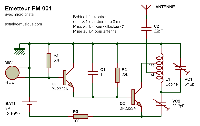
Any sound can be sent to any FM radio from any room by this simple 2-transistor audio transmitter.

Explanation

During the usage, the radio and the audio transmitter should both be in the same frequency between 80-100MHz. Depending on the quality of the device and the parts used, the range can reach at least 100 feet or longer. With this specific device, a very high quality or solid performance can’t be expected since it is one of the most basic transmitter circuits. The transmitter works like 2 independent stages. Some of the components include a 3V or 9V battery power supply, electret microphone, 6”-12” insulated wire antenna, capacitors, transistors, resistors, and a coil.

Most of the parts can be taken from an on radio, TV, or RF based circuit board to avoid purchasing new ones. Any small signal NPN transistor can be used for the two transistors. It could be generic type for as long as the specification is close enough to the important parameters which can be seen in the datasheet. Only the small adjustable capacitor needs to be purchased but there is also an alternative solution without the need for trimmer capacitor

Features of Radio Mobile

Radio Mobile-Main Windows

Radio Mobile is a free and powerful tool for plotting RF patterns and predicting the performance of radio systems. Using freely available terrain elevation data it can produce grey scale, x-ray and rainbow colored virtual maps. One can also produce 3-D and stereoscopic views as well as flyby animations. Background images can be merged with scanned maps, satellite photos and Mapquest maps to produce accurate prediction plots. You can obtain your copy of Radio Mobile from the official website.

Installing Radio Mobile
There are two ways to install Radio Mobile. You can either download the installer file available through this website or download the individual compressed files from the Radio Mobile website or the QSL.net mirror.

Obtaining Elevation Data
Before you can really do anything with Radio Mobile you need to obtain the proper elevation data for the area in which you are creating plots. Radio Mobile accepts elevations in a number of formats including SRTM, DTED and GTOPO30. Fortunately most of this data is available free of charge and with a little effort is easily installed.

Installing Elevation Data
You have downloaded some elevation data you first need to extract it and then configure Radio Mobile so that it can find it. If you downloaded GTOPO30 or DTED data from the sites mentioned previously you may notice the files have the extension tar.gz. In the UNIX world this is known as a “tarball” and this short 7-Zip Tutorial will show you how to extract the data contained within the tarball you downloaded.

Creating A Map
You have Radio Mobile configured to use your elevation data you can begin creating maps. Click on File | Map Properties and you will again be presented with the Map Properties window. This time make sure you uncheck “ignore missing files” and have SRTM set as one of your data sources. The reason for doing this is to get Radio Mobile to tell you which SRTM data files are missing so you download the missing pieces. There are some holes in the SRTM coverage so there is a chance you will not be able to download the missing files. If this is the case check “ignore missing files” after you have filled in as many missing pieces as possible.


Advertisement