an op amp and ic based Full wave rectifier

an op amp and ic based  Full wave rectifier

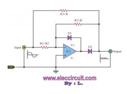
This circuit acts rectifier the ACV signal.This circuit usually requires two op-amp, but this circuit uses only one op-amp.
The work is easy when a positive input into, The D1, D2 will does not work. The output is equal to R2 / (R2 + R3).When V1 is the input signal and R2 = R3 = R, we will have the output signal V0 = 1 / 2 V1.
Later, when the negative output signal into. The D2 to conduct, but D1 does not work. When this circuit is the inverting circuit, output has values V0 = R2/R1 V1, where R1 = 2R, and R2 = R, so V0 = 0.5 V1.
This piece was positive, but the same direction, so the output out.

S:eleccircuit.com

two LT1398’s from Linear Technology used to create buffered color-difference signals from RGB (red-green-blue) inputs

two LT1398’s from Linear Technology used to create buffered color-difference signals from RGB (red-green-blue) inputs
The circuit diagram shows two LT1398’s from Linear Technology used to create buffered color-difference signals from RGB (red-green-blue) inputs. In this application, the R input arrives via 75? coax. It is routed to the non-inverting input of amplifier IC1a and to 1.07-k? resistor, R8. There is also an 80.6-? termination resistor R11, which yields a 75-? input impedance at the R input when considered in parallel with R8. R8 connects to the inverting input of a second LT1398 amplifier (IC1b), which also sums the weighted G and B inputs to create a –0.5Y output.
Yet another LT1398 amplifier, IC2a, then takes the –0.5Y output and amplifies it by a gain of –2, resulting in the +Y output. Amplifier IC1a is configured for a non-inverting gain of 2 with the bottom of the gain resistor R2 tied to the Y output. The output IC1a thus results in the color-difference output R–Y. The B input is similar to the R input. Here, R13 when considered in parallel with R10 yields a 75-? input impedance. R10 also connects to the inverting input of ampli?er IC1b, adding the B contribution to the Y signal as discussed above.
Source : www.extremecircuits.net

16- Bit A/D converter with LCD and PIC18F2550

16- Bit  A/D converter  with LCD and PIC18F2550

The analog to digital converter (ADC) is a commonly required in most of the projects. Analog voltage measurement can be done using the ADC hardware built in together in a PIC. The picture below show a simple setup for measuring the voltage through the adjustment of the potentiometer. PIC used in this example come with a 10 bit ADC. In the picture the hex value shown is the ADC value acquired from the hardware. After a simple conversion the voltage can be obtain from this value.
The next step would be to configure the register on the PIC for the ADC to operate. ADCON0 sets the refrence voltage to Vdd and Vss and select AN0 as the input for the ADC. ADCON1 configure the PIN as analog input. Only PIN AN0 is selected as analog input in this example. ADCON2 sets the required time for acquisition. The value for TAD is choose based on the calculation in the datasheet (pic18f2455, page 298-299). ADC module is turn on for it to function. To display the floating point number conversion to string must be done. The function sprintf is use to format the output so that it can be showed on the LCD. The sprintf function provided by C18 can’t be used directly on a floating point number, so the number must 1st be breakup in to the digits left and right of the decimal point. The sprintf is used to join up the 2 parts and the floating point number is display out on the 2×16 lcd. A routine for reading of ADC value is created. The acquisition is started by setting the GO bit in ADCON0. Conversion is done when the done bits turn 0. The high and low byte of the ADC results are joined in to a 16 bit data and pass back from the function. A simple formula can be use to calculate the voltage from the ADC result. The result is multiply by the max value of reference voltage and divided by 1024. Doing this will obtain the voltage on the pin AN0.

S:www.enmcu.com

Measure temperature safely with the Laser Temp-Gun HVAC Kit

Tags
 Measure temperature safely with the Laser Temp-Gun HVAC Kit


Measure temperature safely and accurately with the Milwaukee 2277-21 12V Laser Temp-Gun Thermometer Kit with Humidity and Dew Point. Ideal for electricians, HVAC/R technicians, general contractors, construction workers, and plumbing professionals, this kit contains the easy-to-use 2277-20 thermometer, a Milwaukee Test & Measure tool that identifies hot spots, prevents damage to electrical equipment, and checks the status of your project as it progresses.
S:eleccircuit.com

Measure temperature safely with the Laser Temp-Gun

Tags
Measure temperature safely with the  Laser Temp-Gun


Measure temperature safely and accurately with the Milwaukee 2277-21 12V Laser Temp-Gun Thermometer Kit with Humidity and Dew Point. Ideal for electricians, HVAC/R technicians, general contractors, construction workers, and plumbing professionals, this kit contains the easy-to-use 2277-20 thermometer, a Milwaukee Test & Measure tool that identifies hot spots, prevents damage to electrical equipment, and checks the status of your project as it progresses.

IC 741 based Bar graph light meter

Tags
IC 741 based Bar graph light meter

If you want simple meter the intensity of the light in a simple way. This circuit is very interesting, because with a LED display with 5 levels.The main equipment is uA741 the most popular op-amp circuit, to used the photo transistor is a device for receiver a lighting to change is electricity very low. We use IC1 acts boost up current, or to compare the voltage levels.The VR1 adjusts the offset voltage to the LED display complete , the intensity of light to measure.The power supply size use +9 V and -9V.

Using IC 741 for Audible light sensor

Tags
Using IC 741 for Audible light sensor

This is audible light sensor circuit that is based the IC741 op-amp IC. This circuit light sensor one,these are use two LDRs for detector lower lightly.
The 741 is pulse oscillator generator output to small speaker. The VR1 have value 50k acts as to fine sensitivity of light sensor. The speaker use small size only because output has low current.

S:eleccircuit.com

CMOS IC 4011 based easy dry cell charger

Tags

The dry cell charger circuit can be fully charged about 12 hours.When used with a 9 volt supply,the equipments in the circuit for the AA type cell.When using the C and D type cell, should reduce the value of the resistance Rx to be 68 ohms.In charge of the cell, you should not be charged to the same series, may cause cell damage is fully charged.
If the cell voltage is below 1.6 volt,The compared circuit to leave the square wave oscillator by the CMOS gate,then the transistor made a charge until the cell voltage is 1.6 volt.The comparison circuit will cut the charging LED blinks, notice prevents over-charging.

S:eleccircuit.com

Solar charging kit 60 watt

Tags
Solar charging kit 60 watt
I’m do looking to backup energy for my laptop, The 60 Watt Solar Charging Kit is need for me very much, it low cost but Good quality,saving money very much.

Example review
I can run my laptop all day, as well as recharge the cell phones and Wifi remotes. My husband can also run his laptop. If we only get on the laptops after work, we can run them well into the night. I’ve had to switch to grid power a couple of times if I’ve used my laptop all day, but I’ve never had to switch over if I’ve only used it during the evening. (This doesn’t count the few rainy days we’ve had. Yes, once in a while it rains in Phoenix.)

This is not the most efficient solar panel set, but it’s very good for starting out and learning about solar power. It’s inexpensive enough to set up and charge all your rechargeable stuff whenever you need it, as long as you live in a fairly sunny area. [...] by C.Bayne.

S:eleccircuit.com

Single transistor based automatic battery charger circuit

Single transistor based automatic battery charger circuit

The following automatic battery-charger design is created with a circuit that could qualify as the simplest window comparator ever built around a single transistor. It starts charging when the battery voltage drops beyond a preset value, and it stops when an upper preset voltage is attained.

With the help of a precise variable voltage supply, the upper and lower voltage levels were set. The normally connected (NC) lead of the relay isn’t joined to the 15-V dc supply, which blocks this voltage from passing to the battery leads. This will accurately set the upper and lower levels. But the charging supply of 15 V dc was connected to the circuit.

First, the variable supply is fixed at 13.3 V dc—the voltage of a fully charged battery—and linked to the battery point of the circuit. The slider of VR1 is turned to the extreme end on the side that’s attached to the positive terminal of the battery. VR2′s slider should be turned toward the end that’s connected to VR1. The transistor turns on, shunting VR1. Then the slider of VR1 is turned toward the other extreme, which is the end connected to VR2.

The test supply voltage is now set to 11.8 V dc, which is the voltage of a drained battery. VR2 is then adjusted so that it just turns off the transistor again. The test voltage is raised to 13.3 V dc again, and VR1 is adjusted so that the transistor turns on. With the upper and lower levels set, the NC point is connected to the circuit (15-V dc charging voltage). Now the battery charger is set and ready to go.

S:/electronicdesign.com

12V SE Digital Battery Tester

Tags
12V SE Digital Battery Tester

Easy-to-use, compact and accurate – pays for itself by reducing harmful battery waste*Works with virtually all replaceable battery types; alkaline, lithium, button, 1.5V – 12V*Fits battery sizes AAA – D, 12V, 9V, camera, watch & hearing aid batteries; 2.5 – 120mA*Easy-to-read meter shows battery strength instantly – no more guessing*Thumb-slide caliper adjusts for battery size; tester requires no internal batteryThe average family spends hundreds-of-dollars a year on expensive replacement batteries for the dozens and dozens of battery-powered devices in their home.
S:eleccircuit.com

Resistance Tester(Internal) For Batteries

Tags
Resistance Tester(Internal) For Batteries

This circuit is designed to check the condition of lead-acid and gel cell batteries with capacities greater than 20Ah. It switches a load of about 18A at a rate close to 50Hz so that the internal resistance of the battery can be measured using a digital multimeter across the battery terminals. The measured AC voltage in millivolts divided by 10 (ie, a shift of the decimal point) is approximately equal to the battery’s internal resistance in milliohms. As shown, the circuit is quite straightforward and is based on two 555 timer ICs (IC1 & IC2) and power Mosfet Q1. IC1 operates as a monostable timer with a period of 10s.

When switch S1 (Test) is pressed, IC1′s pin 3 output goes high for 10s and this enables IC2 which operates as a 50Hz astable oscillator. IC2 in turn drives power Mosfet Q1 which is connected across the load in series with three 0.22W 50W resistors. IC2 then turns off again after 10s – ie, at the end of the monostable timing period. LED1 provides power indication when the circuit is connected to a battery, while LED2 (green) comes on during the test period. The thermostat is not necessary unless the unit is to be used repeatedly (the Jaycar ST-3823 70°C unit is suitable) and you want to protect the output circuit against overheating.

The power Mosfet does not need cooling but the thermostat and the 0.22W 50W resistors should all be mounted on an aluminium heatsink at least 2mm thick. In practice, the internal resistance of car batteries can vary from about 15mW down to about 3mW. Before testing the battery, check that the electrolyte level is correct and that the voltage across its posts exceeds 12.5V for a nominal 12V battery; ie, close to full charge. That done, switch on the car’s headlights and measure the DC voltage between each battery post and its connecting terminal. It should be less than 10mV in both cases; if not, the terminals need cleaning. Once you’ve done that, you can turn off the headlights, connect the tester and proceed with the internal resistance test. Be sure to connect the multimeter’s test probes directly to the battery posts, to read the internal resistance (not the battery terminals).
S:www.extremecircuits.net
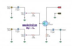
Using FET 2n3819 simple audio mixer circuit

Using  FET 2n3819 simple audio mixer circuit

This circuit, a simple mixer circuit.It can mix two signal channels and one channel is output.Using a codec circuit,Convert stereo audio to mono audio time.
It can increase the number of channels too. By adding a VR1, R1 and C1 to the amount needed. Then connected to Buffett a new one.Most importantly is eating circuit current is very low.Can use with 9-volt batteries immediately.
When entering voice signal, one of input 1 and input 2. Audio is via C1 and C2 of each channel,served coupling signals to VR1 and VR2. To adjust the audio to the Fet Q1.Which it serves, including audio. Then expand signal the output pin S through C3 For coupling signal again, before leaving to the output.

S:eleccircuit.com

FET 2N3819 with 10 minute time delay

FET 2N3819 with 10 minute time delay

This circuit is a basic function of the FET 2N3819, which acts as a switch. In the conduction and not conduction. It runs contrary to the transistor. The circuit can be used to delay the cycle is small. Such as delay, 9-volt light bulb, or motor delay to any DC 9 volts.
When raising the power supply circuit FET Q1 is running. D and S stand by the legs of furniture to the Tong Q1 will flow together, current flows through R2, so the flow from the legs through the leg and S. D, and through R4 to ground. So no current flows into R3 to transistor Q2 does not conduct. Resulting in a voltage appearing at the output is 12 volt, but when I press the S1 switch current flows into the capacitor C1 fully. Then go to the legs G of the FET. Q1 stopped working. Therefore, the current flowing through R2 is flowing to the R3 instead, and to bias transistor Q2 to work on the output transistor Q2 is not working out for 10 minute, because C1 is discharged. The S2 is the reset switch. By acting shock C1 to discharge out soon. That the time delay depends on the C1. If it will delay much longer, if less it will have less delay.

S:eleccircuit.com

BF256 FET Current source

Tags
BF256 FET Current source


This is a constant current source using a FET. This is the most simple replacement to series resistor to limit current.

The N-Channel FET BF256C can give 15mA current.

S:schematics.blogspot.com

LED Driver using constant current source

Tags
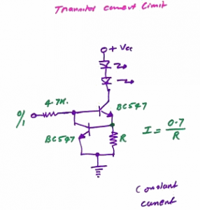
This is a Constant Current Source LED Driver, When the LED driver Upper-NPN is driven by a voltage thru 4.7K the LED lights up. Assume that the Lower-NPN at bottom is absent. The current via LED and NPN is limited by R. 20mA may be ok 15mA even better. Or LED blows even transistor goes.

LED Driver using constant current source


S:schematics.blogspot.com

White LED dimmer (Linear constant current)

Tags
White LED dimmer (Linear constant current)

This simple Linear circuit provides continuously variable regulated current (~25-400mA) from a 4-6 Volt source. I chose a linear design for simplicity, reliability, ease of repair, and to avoid switching EMI in my Cave Radios. The circuit requires only 0.2V headroom above the parallel LED Array voltage to provide regulation at maximum current. The headroom stays low until the LED’s are extinguished at about 0.75V/cell for 4-cell packs.


S:radiolocation.tripod.com

Advertisement