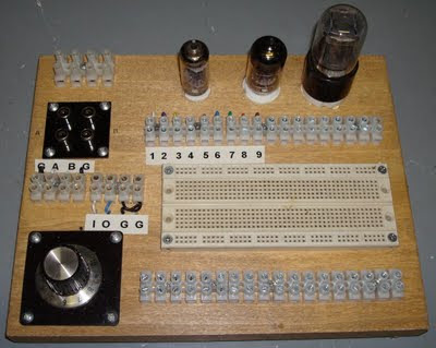
This is a project that I made to take care of an ever increasing need to prototype vacuum tube (valve) circuits. As you can see from the photos, it really is a test “board”. I do a lot of work with tubes and love to design and improve circuits. In the process I often use various CAD type programs to rough out the designs. I have frequently found that the models do not agree with the final build. Some are right on, but most are off enough to turn a good idea into a waste of time. Thus the need to quickly prototype designs. Now I could have created this board with many additional features - speakers, output transformers, LEDs... But what I needed was a simple way to test single stage tube circuits. So for simplicity I wired the tube pins together (pin 1 to pin 1 and so on). The leads from the pins are brought out to terminals on a “Euro” style terminal strip. I included several other “Euro” strips, a pair of RCA jacks, a 100 k-ohm variable resistor and solderless prototype breadboard. This solderless breadboard is available in various sizes from several sources. If you build one of these boards, feel free to use the idea to adapt it to your needs and use whatever parts you so desire.

The hardest part of the build was deciding on the layout of parts. I tried to figure out what kinds of parts would be connected to the various tube pins and place the terminal strips in locations where they would make it easy to swap parts in and out of circuits.
You will certainly notice that there is no power on the board. I have several external variable power supplies and decided they would be fine for prototyping. No need to reinvent the wheel. With a larger board you could easily add power supplies if you desired.
Good listening, Bruce

EmoticonEmoticon