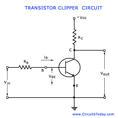
The transistor has two types of linearities —One linearity happens when the transistor passes from cut-in region to the active region. The other linearity occurs when the transistor passes from the active region to the saturation region. When any input signal passes through the transistor, across the boundary between cut-in region and active region, or across the boundary between the active region and saturation region, a portion of the input signal waveform will be clipped off. Portion of the input waveform which keeps the transistor in the active region shall appear at the output without any distortion. In such a case, it is the input current rather than the input voltage that should have the waveform of the signal of interest. Obvious reason is that over a large signal excursion in the active region, the transistor output current responds linearly to the input current but is related quite non-linearly to the input voltage. Therefore, a current drive is used in a transistor clipper, as illustrated in the figure given below.
In the active region, the value of the resistor RB must be large enough when compared to the input resistance of the transistor. The input base current will have the waveform of input voltage and
iB = vin – base-to-emitter cut-in voltage / RB
Waveforms for the transistor clipper for ramp input are shown in the figure given below.


EmoticonEmoticon