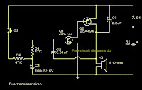
Two transistor siren Circuit Schematic With Explnation
Here is the circuit diagram of a simple two transistor alarm circuit that can be operated from a 9V PP3 battery. Here the two transistors are wired to form an oscillator whose frequency increases when switch S2 is pressed and decreases when S2 is released. In order to attain this the base of Q1 is biased from an RC circuit comprising of R2 and C1.When S2 is pressed C1 is charged through the resistor R2.As the voltage across the C1 increases the time constant decreases and this results in an increases in the frequency. When S2 is released capacitor discharges and the frequency of the tone decreases. The sound heard from the speaker will be almost like that of a siren.
Notes.
* The circuit can be assembled on a Vero board.
* Use a 9V PP3 battery for powering the circuit.
* Switch S2 can be a miniature push button switch.
* The type no of transistors are not very significant here.


EmoticonEmoticon