ACTK 400/600 Watt
Two copies of the powerful unit is able to provide high powwer for long periods. Actrk400 uses 6 n channel MOSFETs in the output stage to about 400 watts into 4 ohms while delivering Actrk600 12 n channel MOSFETs in the output stage of the power supply more than 600 watts into 4 ohms. It has almost achieved Builder 900 watts with Actrk600 graph using 12 IRFP460 MOSFETs.
Actrk 600W schematic
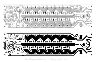
ACTK 400W Layout
ACTK 600W Layout
ACTK Power Supply
Schmatic
Layout power supply
Final Set up And Adjustment
No attempt should be made to set up or test a power amplifier module that is not correctly mounted on
a heatsink. Make sure the main power supply is fused and the work area is clear. First check all your
work and make sure the output devices are insulated from heatsink. The set up is done without an
input or a load connected to the power amplifier.
1. Check the power supply is operating correctly and verify the rail voltages. Switch the power
supply off and check with a multimeter that the rail capacitors have discharged.
2. Using a multimeter measure the resistance of VR2 and set it for maximum resistance.
3. Correctly connect the ground lead, the two positive leads plus the negative lead to the power
amp module.
4. Remove the PCB fuses and replace with 100 ohm 5 watt resistors. Connect a multimeter that
is set to the 20 volt scale across the positive rail 100 ohm resistor.
5. Check that the power supply connections are correct one last time and switch on. If the
multimeter reading goes off-scale, turn off immediately and find the problem. Check also the
100 ohm 5 watt resistors; they may have gone open cct.
6. If everything seems ok adjust VR2 to set the output stage bias current, by measuring the
voltage across the positive rail resistor. Adjust for a reading of 4 volts per output FET pair. I.e.
For a 6 FET board set for a voltage of 12 volts. This equates to a bias current of 40mA per FET
pair or 120 mA total. For the 12 FET board set for a voltage of 24 volts.
7. If everything seems ok, check the output offset voltage and adjust VR1 to achieve an offset of
less than 10 mV. You will need to wait briefly between adjustments for the offset to settle.
8. All being well switch off, back off the bias control trimmer (VR2) and replace the 100 ohm
resistors with 10 ohm 1 watt resistors. Switch on again and re-adjust VR2 to get 0.4 volts per
FET pair.
9. Switch off, remove the resistors and put the fuses back in. Switch on, re-check the offset
voltage and adjust with VR1 if necessary.
The amp module is ready, connect the input and output and enjoy.


