Symasym5_3
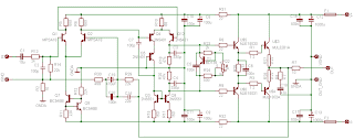
Symasym5, is a "cute" power amplifier, designed with quality but still low price in mind. This resulted in a ClassAB BJT amplifier, using only TO92 transistors for input and VAS, with a reasonable part count. The topology used is well known and consist of a single diffamp for input, plus a 2nd diffamp with current mirror for VAS. This is followed by normal darlington EF outputstage using modern high beta devices. The circuit uses large amounts of feedback over the whole audioband and an unconventional feedback compensation scheme. Right now symasym is designed to be driven directly from a CD/DVD-player, simply place a 22k poslog stereo pot between player and symasym. (as voltage divider)
Schematic
Recomended Part
Symasym5, is a "cute" power amplifier, designed with quality but still low price in mind. This resulted in a ClassAB BJT amplifier, using only TO92 transistors for input and VAS, with a reasonable part count. The topology used is well known and consist of a single diffamp for input, plus a 2nd diffamp with current mirror for VAS. This is followed by normal darlington EF outputstage using modern high beta devices. The circuit uses large amounts of feedback over the whole audioband and an unconventional feedback compensation scheme. Right now symasym is designed to be driven directly from a CD/DVD-player, simply place a 22k poslog stereo pot between player and symasym. (as voltage divider)
Update
The at least change is to reduce C14 from 22pF to 10pF, but i recommend to follow Pavel's advice.
I recommend C14 with 10pF also for MJLs, this increases safety margin.
Do not forget to read Pavel's Review! A very promising evaluation of the qualities to be expected from symasym. Thanks Pavel !
Another update are the resistors R31/32 to be increased from 22ohm to 47ohm.
Symasym5_3 is an update of v5.2, with an improved board layout concerning power gnd, resulting in lower thd for high frequencies, giving more clarity in sound. The Page for symasym5_2 still exists.
If the gain is too high because symasym is driven from preamp, R30 can be increased from 499ohms to 1k, but in this case R16/19 (22 or 33 ohms, not on schematic, REs to Q1/2) are required to keep feedback at same level and
Some Specs
- THD: ~0.005% (measured) sim'd: 0.002%
- Power into 8ohm: 60 watts
- Power into 4ohm: 100 watts
- Gain: 32dB (~1:40) full output at 0.7v input (0.5v rms)
- Feedback: 57dB
- GainBandWidth: ~400Mhz
- Slewrate: ~20v/us (symetrical)
- Supply voltage: +/- 36v
- Biasing: 55ma, ~12mv across a single 0.22 ohm
- Measurings: RMAA Symasym5 The measuring setup itself is far from perfect, but gives a good idea !
- Frequency response: 3.2hz to 145khz (-1db) using 4.7uf input cap
- Phaseshift at 10khz: <3 span="">
- More will follow !
Schematic
Part List
| Device | Qty | Value | Notes |
| Q1,Q2 | 2 | MPSA18 | can be substituted by BC550C (pins reversed !) |
| Q7,Q8 | 2 | BC546B | or maybe 2n5551 (pins reversed !) |
| Q3,Q9 | 2 | 2N5551 | OnSemi/Fairchild/Philips |
| Q4,Q5,Q12 | 3 | 2N5401 | OnSemi/Fairchild/Philips |
| T1 | 1 | BD139 | or bd135, bd135-16 |
| U$5 | 1 | MJE15030 | OnSemi |
| U$6 | 1 | MJE15031 | OnSemi |
| U$3 | 1 | MJL3281A | OnSemi |
| U$4 | 1 | MJL1302A | OnSemi |
| Device | Qty | Value | Notes |
| C14 | 1 | 10pF (has been 22pF) | Mica |
| C2,C7 | 2 | 100pF | Mica |
| C3,C4 | 2 | 330pF | Mica |
| C18 | 1 | 47nF | Wima MKS2 |
| C5, C6, C10, C11, C16, C17, C20 | 7 | 100nF | Wima MKS2 |
| C1 | 1 | 10uF (4.7uF also fits) | Wima MKS2 |
| C8,C9 | 2 | 100uF | Electrolytic 63v (at least 40v) |
| C19 | 1 | 470uF | Electrolytic 16v |
| C12,C13 | 2 | 1000uF | Electrolytic 63v (at least 40v) |
| Device | Qty | Value | Notes |
| R27,R28 | 2 | 0R22 | 5Watts |
| R1, R3 | 2 | 1R2 | 2Watts metal film |
| R4 | 1 | 4R7 | 2Watts metal film |
| R7 | 1 | 10 | 2Watts metal film |
| R2 | 1 | 10 | 250mW metal film |
| R8, R9 | 2 | 22 | 250mW metal film |
| R31, R32 | 2 | 47 (have been 22) | 250mW metal film |
| R26 | 1 | 33 | 250mW metal film |
| R10 | 1 | 68 | 250mW metal film |
| R15,R17 | 2 | 150 | 250mW metal film |
| R11 | 1 | 220 | 250mW metal film |
| R24,R30 | 2 | 499 (or 500) | 250mW metal film |
| R5,R6 | 2 | 680 | 250mW metal film |
| R13,R23 | 2 | 2k | 250mW metal film |
| R12,R14,R29 | 3 | 22k | 250mW metal film |
| R18,R20 | 2 | 47k | 250mW metal film |
| R22 | 1 | 1k pot | Piher, small (470ohm might be better) |
| Device | Qty | Value | Notes |
| F1,F2 | 2 | 2.5T Fuse | Slow blow |
| F1,F2 | 2 | --- | Fuse holder |
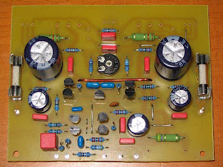
| L1 | 1 | --- | 0.6mm isolated (enamelled) copper wire wounded around R7 forming the output coil. |
- All resistors are standard metal film 250mW except: R1/3/4/7, these are 2W metal film, and the 0.22ohm beeing 5W. Around R7 is wounded a 0.6mm isolated (enamelled) copper wire forming the output coil. (~12 windings) For c19 i used 470uf/16v, all other electrolytics 63v. The 10/100/330pF should be mica-caps. The 100nf and 47nf is recommended to be Wima MKS2 (or better), also for C1 i suggest Wima MKS2, 4.7uf is enough. For Trimpot i use a Piher. The MPSA18 can be substituted by BC550C, for all other parts i do not recommend changes, especially the feedback network (r29/30) should be kept unchanged, feedback compensation is very delicate for this circuit !
- Be careful when substituting the MPSA18 with BC550C, the pinout is reversed between these 2 transistors !!!
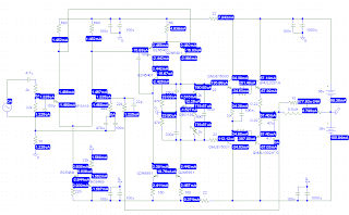
- The bias is adjusted via the trimpot (R22). Recommended bias is 55ma, resulting in 12mv across a single 0.22ohms or 24mv across both 0.22ohms. Connect a DMM to the upper wires of these resistors and adjust trimpot until DMM reads wanted voltage.
Symasym5 biasing: (for debugging)


