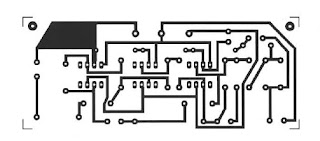
ELECTRONIC BELL: schema and realization
BELL ELECTRONIC SCHEME:
The efalimentation voltage is double, it is between -5 and + + -12V (the
dual mount is perfectly stabilized alimentasion)
Pressing and immediately releasing the button, we get a sound whose frequency is determined by the PI adjustment potentiometer. By regulating the potentiometer P2 for his sharp, the circuit
can come into oscillation emitting a continuous whistle. In this case, we must reduce the sound degradation with potentiometer PI. For mounting of components, follow the layout diagram carefully.
USTE COMPONENTS All resistors are 1/4 watt unless stated otherwise. R = 68 ohmR2 = lKohm R3 = 10 ohms R4 = 470 ohms R5 = 82 ohms R6 = 22 ohms R7 = 270 ohmsR8 = 10 ohms R9 = 47 Kohm Pl = 4,7MohmsA. P2 = 220 Kohm A. Cl = 22uF16Velec.C2 = luF16Velec. C3 = 0.1 uF 100 Vpol. C4 = 0.047 uF 100 Vpol. C5 = 0.047 uF 100 Vpol. C6 = 0.47 uF 100 Vpol. IC1-741 IC2 = 741 IC3 = 741 P = Push. 3 Supports 8-pin.


