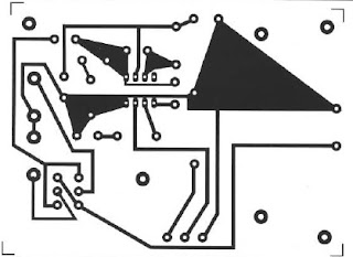
SCHEMA INTERPHONE 2W
SCHEMA INTERPHONE 2W:
This is a very useful editing to communicate between two points.
Its operation requires two speakers who will 1'ecoute el has a remission of different messages. Their impedance should be 4 or 8 Ohms.
When the knob is at rest, the speaker A is one that remains in listening; it is therefore installed near the device.
By pressing the button, the speaker Made microphone function while B goes into listening.
The PI potentiometer is used to adjust the volume and therefore the sensitivity. It must be a stabilized voltage of 9 volts to power the assembly. Given its low consumption (about 6 mA at rest), the system can be powered with a standard 9 volt battery. Maximum output power is about 2 Watts. For assembly of components, it must be attentive to the implementation of components scheme.
LIST OF ELECTRONIC COMPONENTS:
All resistors are 1/4 watt unless otherwise noted.
R = 560hms
R2 = 33 ohms
R3 = 1 Ohm
Pl 47KohmsB =
Cl = 220uF16Velec.
C2 = 100uF16Velec.
C3 = 100uF16Velec.
C4 = 100uF16Velec.
C5 = 270pFceramique.
C7 = 0, lliFceramique.
IC1 = TBA820M
DP = Pushbutton selector.
TR Transformer.
1 Support 8-pin.
Circuit prints mounting 2W INTERPHONE


