FLASHING A SCHEME DOUUBLE BULB CAR AND LOCKS
FLASHING A SCHEME DOUUBLE BULB CAR AND LOCKS:
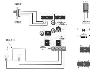
The device allows to flash both lamps simultaneously or alternately.
The Permel DV switch to select the appropriate function, the trimmer TR1 is used to vary the flashing frequency between about 44 and 250 flashes per minute.
The system can be powered by voltages of 12 or 24 Volts DC and the maximum power of each lamp should not exceed 24 Watts if supplies 12 Volts and 48 Watts if supplies 24 Volts.
Naturally, if it is powered by 12 volts, the lamps must also be 12 volts; if supplies 24 Volts, the bulbs must be 24 Volts. For the assembly of components and connections, follow the implantation scheme carefully and remember to do both INDICATED bridges on the scheme. The device can be enclosed in a plastic case.
LIST OF ELECTRONIC COMPONENTS All resistors are of 1/4 watt unless statedotherwise. R = 33 ohm R2 = lKohm R3 = lKohm TR1 = 470 Kohm Cl = 100uF25Velec.C2 = 10uF16VeIec. C3 = 4,7uFl6Velec. D1-1N4001 .. .7 T1 = BDX53 T2 = BDX53 IC1 7809 = IC2 = 4017B IC3-40106B 1 Selector 1 contacts Terminal 5 1 Support pin 14 1 Support 16 pin


