Showing posts with label Am Transmitter. Show all posts

Long range AM transmitter Circuit Schematic With Explnation


Long range AM transmitter Circuit Schematic With Explnation
This is a long range transmitter.This circuit can send signals up to 2km.So that you have to use 1m copper wire.The power of this transmitter has been increased by usin two transistors. When you use this transmitter do give power with out connecting the antenna.Because it will burn your transistors.


Long range AM transmitter Circuit Schematic With Explnation


Note


# The transformer T1 can be a general purpose audio driver transformer seen in transistor radios.

# The inductor L1 can be made by making 56 turns of 365 WG enameled copper wire on a 1 cm former.

# Inductor L2 can be a 10 mH general purpose radio frequency choke.

# The circuit can be powered from a 9V PP3 battery.

5 to 500 feet transmitter Circuit Schematic With Explnation


5 to 500 feet transmitter Circuit Schematic With Explnation
This is so useful circuit because this circuit can transmit signals 5 feet to 500 feet.Here I have used common transistor 2N5225 If you are unable to find this you can use any general purpose transistor.

5 to 500 feet transmitter Circuit Schematic With Explnation

Note

# About L1 is mentioned on the picture

# This circuit operates with 9V DC

# use 5cm wire as an antenna

Parts and schematic for an AM radio transmitter

Small components needed to build an AM radio transmitter :
- 555 timer chip
- NPN transistor
- two #103 capacitors (0.01 microfarads or 10,000 picofarads)
- #102 capacitor (0.001 microfarads or 1,000 picofarads)
- some short wires
- two 1 Kilohm resistors
- 10 Kilohm resistor
- 1/8 inch (3.5 millimeter) female audio jack (yours may have more or less than three
wires, but it must have at least two)
- 5 Kilohm potentiometer

Bigger Stuff:

- 1/8 inch (3.5 millimeter) male audio cable
- AM radio receiver
- Antenna. Yours doesn't have to be made out of a pop can, but the pop can works
- Breadboard
Schematic
:

Parts and schematic for an AM radio transmitterS:www.instructables.com

a very simple AM voice transmitter construction

If a crystal radio is the distilled essence of a radio, this transmitter is the matching distilled essence of transmitters.

The transmitter goes together in about 10 minutes, and is small enough to fit in the palm of your hand.

 a very simple AM voice transmitter construction

Depending on the antenna, the transmitter can send voice and music across the room, or across the street.

I put together my first version with simple clip leads (no soldering, no printed circuit board, not even a battery clip). This version is much sturdier and convenient.

S:sci-toys.com

74HC240 Qrp Transmitter.


Description.

The ARRL HB describes an experimental 0.5W transmitter that uses a 74HC240 octal inverting buffer. One section is used as a fundamental frequency oscillator, four sections are used as an amplifier, while three sections are grounded, and unused. The three unused sections can be put to use in further expansion into a TCVR. Q1 is used to key the transmitter, while the 7808 provides a stable 8V DC supply. THe IC will dissipate heat, and a heat sink should be glued onto it using epoxy. The low pass filter is standard, and the values for some HF bands are given in the table above. This design forms the basis of a minimal QRP TCVR that I am developing, as part of my education in electronics.

http://www.qsl.net/5z4ft/74hc240qrp.html

1W AM Transmitter circuit and explanation


This AM transmitter circuit provides a nice, clean output of about 1 Watt (carrier power). Though designed for the medium wave band (circa 1.5 MHz) it would work equally well on higher frequencies (6.2 MHz for example) with a few tweaks in component values (see table on left - C15 should be adjusted for maximum output).


The carrier (produced by the 4049) is modulated at low-level by the MC1496 balanced modulator. There are then a couple of stages of linear amplification to reach the final output power so no modulation transformer is required. TR2, TR5 and TR6 are BC108 or similar; TR3 is a 2N3053 or 2N4427 or 2N3866 or any low/medium power NPN transistor. The main output transistors, TR4 and TR5 were originally 2SC1162 but BD135 or BD139 or other medium power RF transistors will do equally well. T1 uses a pre-tuned TOKO KANK3334 coil, the other transformers are wound on the red T50-2 toroids (the number of turns shown is the ratio, use about 4 to 5 times that number in reality - less at higher frequencies). The LED lights up if current in the output amplifier goes too high, so it's a kind of 'high SWR' warning.

Source: ZFM

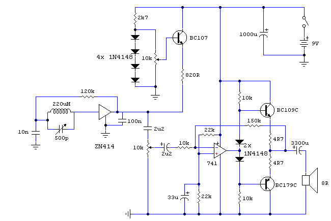
ZN414 Portable AM Receiver circuit and description

Notes:
Designed around the popular ZN414 ic this receiver covers the AM band from 550 - 1600 KHz with the values shown. For Longwave the coil needs to be changed. Use one from an old MW radio to save time. The ZN414 is a tuned radio frequency designed and incorporates several RF stages and an AM detector. It is easily overloaded and the operating voltage is critical to achieve good results.

The BC107 acts as a voltage follower, the four 1N4148 diodes providing a stable 2.4V supply. With the 10k pot , which acts as a selectivity control, and the b-e voltage drop of the BC107, the operating voltage for the ZN414 is variable from 0 to 1.8volts DC. If you live in an area that is permeated with strong radio signals, then the voltage will need to be decreased. I found optimum performance with a supply of around 1.2 volts.

Circuit diagram

The audio amplifier is built around an inverting 741 op-amp. Extra current boost is provided using the BC109 / BC179 complementary transistor pair. The voltage gain of the complete audio amplifier is around 15. The audio output of the complete receiver is really quite good and free from distortion. I may provide some sound samples later..


author: Andy Collinson
e-mail:
web site: http://www.zen22142.zen.co.uk

Advertisement