Showing posts with label Subwoofer. Show all posts

Subwoofer project using MAW-10 driver

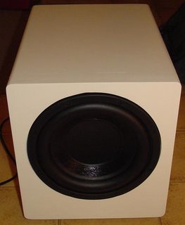
I am slowly working on getting my new site up and going, but in the meantime, I did manage to put the finishing touches on a DIY Subwoofer project. Below is the front view of a ported subwoofer project using a MAW-10 driver from www.mach5audio.com.

DIY Subwoofer Project

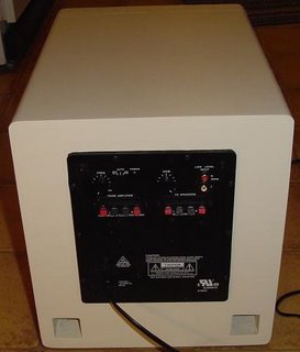
The enclosure is constructed from 3/4" MDF and active power is supplied by a partsexpress plate amplifier. On the underside of the enclosure is a speaker terminal so I can switch between passive and active power. The enclosure was finished with the same cream color paint used on the DIY Fostex FE127E Sealed Bipole Speaker Project.

MAW-10 DIY Subwoofer Project
The driver is still breaking in, but it already outperforms my JBL PB10.

detail about Isobaric 6th Order Bandpass Subwoofer

Dan McGrath (from Great Britain) sent an email with a link to his recent DIY Subwoofer project. For the subwoofer project, Dan decided to use an Isobaric Sixth Order Series-Tuned Bandpass enclosure. The basic layout of a 6th order isobaric bandpass enclosure is shown in the figure below.

Isobaric 6th Order Bandpass Subwoofer Speaker Box
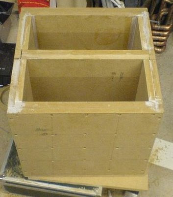
The enclosure was constructed using Medium-Density Fiberboard (MDF) which is inexpensive and easy to work with. To make the enclosure rigid, Dan doubled up the MDF as shown below (click photo to enlarge).

DIY Isobaric Sixth Order Bandpass Subwoofer Construction
For the subwoofer project Dan used two Eminence Beta 10 drivers. The Eminence Beta 10 is an 8 ohm, 10 inch bass driver with a power rating of 250W and a sensitivity 97 dB. With the very high efficiency of these drivers, the subwoofer will be able to produce high SPL with only modest power. The Eminence Beta 10 is readily available (often locally) and it is relatively inexpensive. The photo below (click to enlarge) shows the two drivers in the baffle.

DIY Isobaric Sixth Order Bandpass Subwoofer Box
The finished subwoofer enclosure is shown in the photo below (click to enlarge). Dan has been using the subwoofer for a few months now and is very pleased with the results. That should not come as a surprise considering the level of effort he put in to this build. Very nice work Dan.

DIY Isobaric 6th Order Bandpass Subwoofer

Mini Subwoofer 5″ – 6″ BandPass 4th Order Isobaric


The order of 4 or sealed rear chamber bandpass system is essentially a system of watertight enclosures with the addition of an acoustic filter for the driver. The resulting system usually provides a lower cut-off frequency, the compromise that a larger case. The space can be reduced by two drivers in isobaric configuration.

4th-order bandpass systems generally show better able to handle the functions that the other major systems are considered. The transient response and is second only to the sealed enclosure systems, making it a good choice for subwoofer applications.

Since all output 4th order bandpass system is via the port, the largest diameter possible for the port area should be used to minimize noise from the port. The ports must be incinerated where possible, for the same reasons.


4th order Ssobaric Subwoofer Box Design

The 4th order bandpass system rarely allows a perfect bandpass response - there is usually an out-of-band noise present in the production. A notch filter can be used simply to reduce the noise as audible. Otherwise, a lowpass filter used in series with the driver, but the in-band response system may be affected if this approach is taken.

As the speaker sound 4th order band pass issued by the openings or ports on the port side of the box, the port noise inevitable.

This unwanted noise can be minimized by a notch filter and the largest diameter possible for the port of the area should definitely be used. Another option is to burn the ports of the 4th order bandpass room as this will certainly help to reduce unwanted extra from the subwoofer.

Mini SubWoofer Power Amplifier clik for detail

WOOFER / MID MODEL - 5MP60 / N

Specifications
Nominal Basket Diameter 5 "/ 125mm
Impedance 8 ohm
RMS Power 50 Watts
Program Power 100 Watts
Frequency response 50Hz - 12.0kHz
Sensitivity (1W/1m) 91dB
Voice Coil Diameter 1 "/ 25.8mm
BL Factor 6.4 N / A
Voice Coil Length 14 mm
Air Gap Height 6mm
X Damage (peak to peak) 20 mm
Magnetic Assembly Weight 2.2 lbs / 1.0 kg.
Edit Information
Diameter 5.28 "/ 134mm x 5.28" / 134mm
Bolt Circle Diameter 5.4 "/ 137mm
Baffle Cutout Diameter --
- Front Mount 4.72 "/ 120mm
Many of the 4 mounting holes
Volume displaced by driver, 019 m 3 / .5 liter
Total Depth 2.68 "/ 68mm
Net weight 2.64 lbs / 1.2 kg.
Weight 2.8 lbs / 1.27 kg.
Materials
Basketball aluminum diecast
Polypropylene cone
Rubber Surround
Voice Coil Wire Copper
Ferrite
Thiele-Small Parameters
Resonance Frequency (FS) 60 Hz
Impedance (Re) 5.33 ohms
Coil Inductance (Le) 0.4 mH
Mechanical Q (Qms) 1.604
Electrical Factor (Qes) .35
Total Q (Qts) .29
Comp. Equivalent Vol. (Vas) 35 FT3 / 9.8 Liter
Voice Coil Overhang (Xmax) 4.0mm
Reference yield 5%
Volume Displacement 34 cm3

Isobaric 4th order Bandpass Subwoofer Box Design


The fact that we need a subwoofer means that something is missing in the performance of the main speakers. This is not surprising, since the speakers unfortunately have to coexist with families, women and companions, leading to the inevitable Compact, stand-mounted speaker. Modern, compact speakers are excellent performances, but there is no further away from the laws of physics, small box = bad bass. So, modern speakers designed for a response in the low-limit?

User isobaric subwoofer on the Altec Lansing FX4021 and FX5051


4th isobaric subwoofer box design

The subwoofer is a bit of a word misnomer. It includes sub-audio course can not hear you. We mean really low sound. This does not mean we can not "collect" the sub-audio frequencies. The body can not perform under the form of audio-frequency vibrations and can strengthen the reality of the listening experience. There is usually little more low audio below 20Hz in most of the music.

The only (not electronic), an instrument can produce something in this Church is the body 16.67Hz. Even if this body is equipped with the solid pipe is usually filled with something to prevent the building collapsing around!

For practical reasons we can arrange to 20Hz as the lowest audio frequency that we want to reproduce, may be less than that, the boxes are often quite large. OK. So who determines the lowest frequency we want the subwoofer to handle, but what about the highest frequency?
It is easy to match the response of the existing speakers.

In my case, my speakers are-3dB at 47Hz. That is a lot better than most small speakers, 70-80Hz at-3dB is fairly typical. Ideally the subwoofer to be on the same-3dB frequency. It is easy acheivable a low-pass electronic filter. These can easily be made adjustable to fit almost all existing stakeholders.

Why only one subwoofer, we have two for stereo? The answer to this depends on how the human ear perceives direction. The brains very carefully compares the phase of sounds in the left ear or right and take a decision on this basis.

At high frequencies, the distance between the ears is an important part of the wavelength and the phase difference is large. Because the frequency is reduced, the distance between the ears small compared to the wavelength.

The phase difference is reduced making it difficult for the brains towards the sound calculates. It is not by any means the whole story, the ears also use the level difference and the slight head movements to better determine the direction. Below 200Hz, the human auditory system is almost fully able to determine direction, so it does not matter if the bass is in stereo, mono or even in the room where it originated.

Thus, a subwoofer is all you need. It is normal that the sum of the left and right channels within the subwoofer, so no information is lost. Joint Stereo is often used in the MP3 coding scheme. The low frequencies are encoded in mono, stereo at higher frequencies.

I have several cheap 180 mm / 6.5 "drives and carefully measured their parameters. This step is crucial in this kind of design that even small errors affect the frequency response drastically.

I used my speaker WinISD and added to the database to track the response and the size of the box to calculate. Compromises are necessary in this kind of design. You can find a good performance and a very narrow bandwidth or poor performance and a wider bandwidth. What is acheivable entirely dependent on the properties of the drive. I was fortunate in that my 3 pounds produced a pilot-3dB bandwidth of 29-76Hz. I can not change, but I could filter out the high-end to match my existing speakers.

I decided to use a configuration with two drive Isobaric back to back. This has the advantage of reducing by half the required volume of the two halves of the bandpass enclosure.

One effect of the tax Isobaric half volumes needed in contrast to cases where a driver was used. Another is that the port setting remains the same, but half of the volume, equivalent to a doubling of the port.

Note in the above table, the port is 401mm long. There is no place for him in the cavity 11 liter before with a little thought Latteral was necessary for the host. Some ideas are not at this point if the port can not be physically made to adapt. In this example, I solved this problem with the design.

Subwoofer Box Spec:


Number of cores 2 (used as an installation isobaric) 4th Order Bandpass Box Type Box dimensions for chamber 11.0 liters 24.5 liters Achterhuis Port tuning frequency of 46.56 Hz Wind 1 Wind -> Front Room from 0401 to 0060 m long x 0.060 m square
22 Watts Mini Subwoofer Circuit TDA1516 with Adjustable Frequency The subwoofer is a subwoofer or a speaker to reproduce low frequencies, devotee of

22 Watts Mini Subwoofer Circuit TDA1516 with Adjustable Frequency

The subwoofer is a subwoofer or a speaker to reproduce low frequencies, devotee of 20 Hz to 150 Hz electronic circuit diagram below shows the details of a scheme of the main amplifier TDA1516 22 watt in 4 ohm car subwoofer driver. This device is designed for an existing stereo amplifier, often requires adding another blow to the music of driving a subwoofer.

The amplifier uses BTL is a good and cheap ((Bridge Tied Load channels) 13-pin IC TDA1516 from Philips is now NXP Semiconductors), which may provide a small number of components and 22W at 4 ohm load voltage 12 volt car battery default.

The device consists of several parts: the name of the potentiometer, dual-linear motion potentiometers, 1/4W resistors, capacitors, electrolytic 25V, 63V Polyester capacitors, LED, 100 mA NPN transistor, dual BIFET Op-Amp, 24 W BTL car radio RCA audio input amplifier and two speakers 4 ohm or 8 ohm woofers in isobaric parallel wiring.


DIY 12 volt car project Subwoofer frequency low-pass filter circuit and BTL Amplifier TDA1516

The signals from the line outputs for stereo mixing amplifier input drive, and taking into account the level of the signal to the buffer and can be reversed IC1A phase SW1. Such control may be useful to the subwoofer in phase with the speaker of the existing car radio.

Then, a variable frequency 12dB/octave-pass low IC1B, the components of the Q1 and then you can pass the low frequency of 70 Hz or 150 Q2, R17 and C9 form a voltage stabilizer to facilitate access and filtering circuit to prevent track of the services given power at a low level positive.

LPF subwoofer and amplifier parts list:


Potentiometer
P1-10K
P2-22K

Resistor
R1, R4-1K
R2, R3, R5, R6-10K
R7, R8-100K
R9, R10, R13-47K
R11, R12-15K
R14, R15, R17-47K
R16 6K8
R18-1K5

Capacitor
C1, C2, C3, C6-4μ7 25V
C4, C5-68NF 63V
C7 33nF 63V
C8, C9 220μF 25V
C10 470nF 63V
C11 100nF 63V
C12 2200uF 25V

Diode
D1 LED Lamp

Transistor
Q1, Q2 BC547

IC
IC1-TL072 Op-Amp
IC2-TDA1516BQ Car Amplifier 24 Watt BTL

Switch
SW1-Toggle SPDT
SW2-Toggle SPDT

RCA Jack
J1, J2 RCA Audio Input

SubWoofer Drive Unit
4-ohm woofer driver or two 8 ohm woofers connected to Isobaric

Mini Subwoofer 5″ – 6″ BandPass 4th Order Isobaric The order of 4 or sealed rear chamber bandpass system is essentially a system of watertight enclos

Mini Subwoofer 5″ – 6″ BandPass 4th Order Isobaric

The order of 4 or sealed rear chamber bandpass system is essentially a system of watertight enclosures with the addition of an acoustic filter for the driver. The resulting system usually provides a lower cut-off frequency, the compromise that a larger case. The space can be reduced by two drivers in isobaric configuration.

4th-order bandpass systems generally show better able to handle the functions that the other major systems are considered. The transient response and is second only to the sealed enclosure systems, making it a good choice for subwoofer applications.

Since all output 4th order bandpass system is via the port, the largest diameter possible for the port area should be used to minimize noise from the port. The ports must be incinerated where possible, for the same reasons.


4th order Ssobaric Subwoofer Box Design

The 4th order bandpass system rarely allows a perfect bandpass response - there is usually an out-of-band noise present in the production. A notch filter can be used simply to reduce the noise as audible. Otherwise, a lowpass filter used in series with the driver, but the in-band response system may be affected if this approach is taken.

As the speaker sound 4th order band pass issued by the openings or ports on the port side of the box, the port noise inevitable.

This unwanted noise can be minimized by a notch filter and the largest diameter possible for the port of the area should definitely be used. Another option is to burn the ports of the 4th order bandpass room as this will certainly help to reduce unwanted extra from the subwoofer.

Mini SubWoofer Power Amplifier clik for detail

WOOFER / MID MODEL - 5MP60 / N

Specifications
Nominal Basket Diameter 5 "/ 125mm
Impedance 8 ohm
RMS Power 50 Watts
Program Power 100 Watts
Frequency response 50Hz - 12.0kHz
Sensitivity (1W/1m) 91dB
Voice Coil Diameter 1 "/ 25.8mm
BL Factor 6.4 N / A
Voice Coil Length 14 mm
Air Gap Height 6mm
X Damage (peak to peak) 20 mm
Magnetic Assembly Weight 2.2 lbs / 1.0 kg.
Edit Information
Diameter 5.28 "/ 134mm x 5.28" / 134mm
Bolt Circle Diameter 5.4 "/ 137mm
Baffle Cutout Diameter --
- Front Mount 4.72 "/ 120mm
Many of the 4 mounting holes
Volume displaced by driver, 019 m 3 / .5 liter
Total Depth 2.68 "/ 68mm
Net weight 2.64 lbs / 1.2 kg.
Weight 2.8 lbs / 1.27 kg.
Materials
Basketball aluminum diecast
Polypropylene cone
Rubber Surround
Voice Coil Wire Copper
Ferrite
Thiele-Small Parameters
Resonance Frequency (FS) 60 Hz
Impedance (Re) 5.33 ohms
Coil Inductance (Le) 0.4 mH
Mechanical Q (Qms) 1.604
Electrical Factor (Qes) .35
Total Q (Qts) .29
Comp. Equivalent Vol. (Vas) 35 FT3 / 9.8 Liter
Voice Coil Overhang (Xmax) 4.0mm
Reference yield 5%
Volume Displacement 34 cm3

Isobaric 4th order Bandpass Subwoofer Box Design The fact that we need a subwoofer means that something is missing in the performance of the main spe

Isobaric 4th order Bandpass Subwoofer Box Design

The fact that we need a subwoofer means that something is missing in the performance of the main speakers. This is not surprising, since the speakers unfortunately have to coexist with families, women and companions, leading to the inevitable Compact, stand-mounted speaker. Modern, compact speakers are excellent performances, but there is no further away from the laws of physics, small box = bad bass. So, modern speakers designed for a response in the low-limit?

User isobaric subwoofer on the Altec Lansing FX4021 and FX5051


4th isobaric subwoofer box design

The subwoofer is a bit of a word misnomer. It includes sub-audio course can not hear you. We mean really low sound. This does not mean we can not "collect" the sub-audio frequencies. The body can not perform under the form of audio-frequency vibrations and can strengthen the reality of the listening experience. There is usually little more low audio below 20Hz in most of the music.

The only (not electronic), an instrument can produce something in this Church is the body 16.67Hz. Even if this body is equipped with the solid pipe is usually filled with something to prevent the building collapsing around!

For practical reasons we can arrange to 20Hz as the lowest audio frequency that we want to reproduce, may be less than that, the boxes are often quite large. OK. So who determines the lowest frequency we want the subwoofer to handle, but what about the highest frequency?
It is easy to match the response of the existing speakers.

In my case, my speakers are-3dB at 47Hz. That is a lot better than most small speakers, 70-80Hz at-3dB is fairly typical. Ideally the subwoofer to be on the same-3dB frequency. It is easy acheivable a low-pass electronic filter. These can easily be made adjustable to fit almost all existing stakeholders.

Why only one subwoofer, we have two for stereo? The answer to this depends on how the human ear perceives direction. The brains very carefully compares the phase of sounds in the left ear or right and take a decision on this basis.

At high frequencies, the distance between the ears is an important part of the wavelength and the phase difference is large. Because the frequency is reduced, the distance between the ears small compared to the wavelength.

The phase difference is reduced making it difficult for the brains towards the sound calculates. It is not by any means the whole story, the ears also use the level difference and the slight head movements to better determine the direction. Below 200Hz, the human auditory system is almost fully able to determine direction, so it does not matter if the bass is in stereo, mono or even in the room where it originated.

Thus, a subwoofer is all you need. It is normal that the sum of the left and right channels within the subwoofer, so no information is lost. Joint Stereo is often used in the MP3 coding scheme. The low frequencies are encoded in mono, stereo at higher frequencies.

I have several cheap 180 mm / 6.5 "drives and carefully measured their parameters. This step is crucial in this kind of design that even small errors affect the frequency response drastically.

I used my speaker WinISD and added to the database to track the response and the size of the box to calculate. Compromises are necessary in this kind of design. You can find a good performance and a very narrow bandwidth or poor performance and a wider bandwidth. What is acheivable entirely dependent on the properties of the drive. I was fortunate in that my 3 pounds produced a pilot-3dB bandwidth of 29-76Hz. I can not change, but I could filter out the high-end to match my existing speakers.

I decided to use a configuration with two drive Isobaric back to back. This has the advantage of reducing by half the required volume of the two halves of the bandpass enclosure.

One effect of the tax Isobaric half volumes needed in contrast to cases where a driver was used. Another is that the port setting remains the same, but half of the volume, equivalent to a doubling of the port.

Note in the above table, the port is 401mm long. There is no place for him in the cavity 11 liter before with a little thought Latteral was necessary for the host. Some ideas are not at this point if the port can not be physically made to adapt. In this example, I solved this problem with the design.

Subwoofer Box Spec:


Number of cores 2 (used as an installation isobaric) 4th Order Bandpass Box Type Box dimensions for chamber 11.0 liters 24.5 liters Achterhuis Port tuning frequency of 46.56 Hz Wind 1 Wind -> Front Room from 0401 to 0060 m long x 0.060 m square
Advertisement