Showing posts with label preamplifier. Show all posts

SCHEMA PREAMPLIFIER WITH LOW INPUT IMPEDANCE Circuit schematic with explanation

SCHEMA PREAMPLIFIER WITH LOW INPUT IMPEDANCE

 SCHEMA PREAMPLIFIER:

SCHEMA PREAMPLIFIER WITH LOW INPUT IMPEDANCE Circuit schematic with explanation


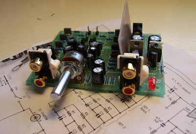
This preamplifier present the characteristic of having a low input impedance, it is therefore perfectly appropriate to be used with magnetic transducers: a low impedance dynamic micro magnetic heads, phone sensors.

SCHEMA PREAMPLIFIER WITH LOW INPUT IMPEDANCE Circuit schematic with explanation


Its amplification is very high, therefore, whether it should be reduced, there should be a series trimmer R3 100 ohms. The system can be powered by a voltage between 9etl8Volts. For its realization, we must
follow the implementation scheme.


LIST OF ELECTRONIC COMPONENTS: All resistors are 1/4 watt unless otherwise noted. R = 1 Kohm R2 = lKohm R3 = 10Kohms R4 = 10Kohras R5 = 10Kohms R6 = 10Kohms R7 = 100Kohms R8 = 100Kohms Cl = 100uF16Velec. C2 = 10uF16Velec . C3 = 4,7uF16Velec. C4 = 47uF16Velec. C5 = 47uF16Velec. T1 BC237 = T2 = BC237 1 clip for 9 volt battery. PRINTED CIRCUIT INPUT PREAMPLIFIER WITH LOW IMPEDANCE


SCHEMA PREAMPLIFIER WITH LOW INPUT IMPEDANCE Circuit schematic with explanation


preamplier (5687 tube based)

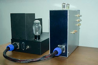
The latest addition to the DIY Audio Projects website is a fine looking tube preamplifier constructed by Vincent Wong. The tube preamp is based around a pair of 5687 twin triodes. Each channel uses both sections of a 5687 tube and LED biasing is used on each section.

DIY 5687 Tube Preamplifier Project
To keep hum at a minimum, the filaments are heated using DC. The power supply is external to the preamp section and consists of a RCA-83 mercury rectifier and two 50H chokes.

DIY 5687 Tube Preamp Project

7812/7912 regulators and moving magnet phono preamplifier

Mark in Australia has put together a moving magnet phono preamplifier using a electronics hobby kit. The phono preamp kit provides everything you need except minus an enclosure and a power supply (AC walwart). The circuitry is contained on a printed circuit board (PCB) and consists of operational amplifiers (opamps) with up to three equalization compensation circuits which can be selected with jumpers or a switch. The kit comes with LM833, but you can use which ever opamp you prefer. The power supply is also on the PCB and uses 7812 / 7912 regulators. The design supports all of the common compensations and several 78 compensations as well.

Phono Preamp Kit
The enclosure and power source need to be provided. For the power supply Mark used a walwart (15VAC) and the circuitry is contained in a plastic (ABS) enclosure. The inputs/output were moved to the rear.

Moving Magnet Phono Preamp Kit Enclosure

comprehensive information to build ECC802S (12AU7 / ECC82) Tube SRPP Pream


Pretty much everything in the preamp is standard tube amplifier construction. However, you do need to follow some standard tube layout and construction procedures. Keep the power and signal wires separated. If they need to cross, do so at right angles. The same is true for resistors and capacitors. Keep signal bearing components away from the power supply filter capacitors and especially transformers. I prefer to place power supply components in one section of a chassis and the signal portion in a separate area at least 2 inches away from the power supply parts. For more design and construction tips, see my Design and Construction of Vacuum Tube Amplifier tips and suggestions. Suggestions for a Tube Amplifier Wiring Color Code are also available.

The tube amplifier power transformer specified in the plans (Edcor XPWR083) is an inexpensive ($15 US, August 2010) PCB mounting type rated, 200 V at 40 mA and 8 V at 1.5 A. It is unshielded and if possible should be either enclosed in a metal enclosure (Photograph 3) or at least separated from the remainder of the circuitry with a shield. There is no reason other transformers can't be used; this one has the right ratings and and is inexpensive.

DIY ECC802S Tube SRPP Preamplifier Project
ForeWatt Type II Preamplifier with remote control circuitry

The heater supply is regulated DC. The heaters must not be connected to the same ground as the signal, B+ or chassis. They need to float or tube failure may occur. The only connection of the heater circuit to the rest of the circuitry is a "bias" tap. This is developed from the main B+ supply and is about 1/3 the B+. No current flows through this connection (perhaps a tiny bit of leakage). It only establishes a reference for the heaters so that the difference between the heaters and any of the cathodes is less than 100 volts. One quirk of SRPP and other "totem pole" circuit configurations is that one of the cathodes is elevated quite a bit above ground. In a SRPP the cathode on the upper triode has a voltage potential of roughly 1/2 the applied B+. So with 215-225 V on the anode the cathode is over 100 V. During start up this value is actually 1/2 the full B+ (of about 275 V). This value exceeds the tube rating for heater to cathode voltage and will result in tube failure. Perhaps this will not occur immediately, but it will as the tube ages. I have had this happen. Not a good thing. It usually results a huge spike in the output that could be catastrophic further down the audio chain.

Use shielded wire from the inputs to the selector switch and to and from the volume control. As there in no provision for channel balance (IMHO no well designed system should need one) use either a quality variable resistor (I use Alps Blues) or a stepped volume control / attenuator.

DIY ECC802S Valve SRPP Preamplifier Project
ForeWatt Type I Preamplifier - Interior View

One area that is always of concern is what to do with the metal chassis if you use one. Most inexperienced builders tie all the grounds to the metal chassis. This is nearly always going to result in ground loops. Depending on your electrical codes (which vary by country) you should connect the chassis (and actually any exposed metal parts like transformers) to the AC mains ground. In the US this is the third wire (supposed to be green). The signal and B+ grounds are connected to the chassis through a type X2 rated capacitor and a resistor in parallel with the capacitor. The capacitor is a special rated type designed just for this application (one brand is RIFA) and will range in value from about 0.1 to 0.33 uF. The resistor is typically a common carbon one of 100-150 ohms and rated at 1/2 Watt. A related mistake made by novice builders is to directly connect the input and output jacks to the chassis. The ground portions of the jacks should go to the "floating" signal ground in the circuit. Either of two types of ground system can be used for the signal and B+. I have used both "star" grounding and "buss" grounding in my projects. Either can work satisfactorily. In this project a modified star ground system is used. One star grounding point was used for each channel with a single connection to the B+ negative.

I used a type a LM317 variable voltage regulator in the heater supply as I am familiar with their operation (and have lots of them), but a fixed voltage regulator like a 7806 can be used as well.

The B+ is filtered through a total of 4 stages. Another thing I don't do is use chokes. I have nothing against them; I just don't need them to get the performance I require. The final filter stage to each tube is isolated from the alternate channel and each uses a polyester capacitor. I have found that using poly (polyester or polypropylene) caps in the final stage seems to improve the overall quality of sound. It is possible that an electrolytic with a suitably sized bypass cap would work well also.

The one component (other than the vacuum tube) that has the most effect on the sonic signature of the preamplifier is the output capacitor. The choice of brand, size and type are significant in this component. I recommend no less than 0.47 uF if you are feeding a high impedance load (50 k-ohms or more and short cables). Values as high as 10 uF are suitable for lower impedance (5 k) loads. I tried several types and sizes and finally settled with a 1 uF Russian K40Y9 paper-in-oil (PIO) capacitor in one version and a 1 uF Jantzen Standard Z capacitor in the other preamp. I suggest you use whatever brand and type you like as it will color the sound a bit. Some types I tried were Auricaps (nice clean sound with a little less bottom end), Jantzen (good overall performance, but not as detailed as the K40Y9), WIMA MKS (OK but not as nice sounding as the K40Y9), a cheap unnamed one (to protect the innocent) - it was horrible, bass OK, everything else edgy and not really listenable). So pick something you like.

The remote control portion of the second type of preamp is powered separately by a small 12 volt SMPS. Any kind of 12V power source will work fine provided it can deliver over 600 mA. It must be a type that is isolated from the AC line as the inputs and control circuitry are attached to the negative side of the 12 volts. It cannot use the same power source as the tube heaters as they have a positive bias on them to protect the heaters and cathodes from failure as noted earlier. See the schematics for the components I used. The instructions provided with the remote control module are a bit unclear so be sure to watch the interconnections. I misconnected them several times apparently without damage. Another thing that was confusing was that the module automatically selected input 2 on start up. This is not really a problem; just connect the component you use most to that input.

I used relays and a switch to activate the bypass function. The relays can operate off the same power supply as the remote control module. Just be sure there is sufficient current available. I used an underpowered one at first and had the relays chatter when the motorized volume control was operating. Very bad for the speakers. The MV-02 motorized remote volume control module is approximately $35US (August 2010). Remember that there can be significant shipping costs on items from Hong Kong so check first. It comes complete with the hand held remote control. It is a collection of assemblies that interconnect with ribbon cables. The instructions are a bit vague so read them carefully. Out of a total of five MV-02 motorized remote volume control that were ordered, one failed to operate properly. Despite the one DOA module, they are still a great buy. It the MV-02 comes with an Alps Black 100k stereo motor volume control. This potentiometer alone is worth the price. You can design a "passive" preamplifier around the module itself. Essentially, the bypass mode in the Type II schematic is just that. The indicator LEDs are not included, so you will need to provide your own. A series resistor of about 2 k is required for use with them. Since the module uses a common signal and power ground it could not be powered from the existing preamp power supply. I used a Mean Well PM-05-12 SMPS module to power it. This SMPS takes 100-240 VAC and converts it to 12 VDC. Importantly, it has 1000 volts of isolation of the inputs to the outputs. I attach it main power supply just after the power switch.

information to construct tube preamp for guitar with tone control

I decided recently to build a tube preamp for my home studio. Please note, however, that this is not a circuit for the novice electronics builder. The circuit itself is simple, but unlike most semiconductor projects, this one uses voltages near 300V. The danger of electrocution is present and neither the author can assume responsibility for protecting you.
If you are not familiar with good construction and safety practices for high – voltage electronics, do not attempt to build this circuit.
So how does it sound?
This preamp won’t make the sound of an overdriven Marshall stack, nor is it a heavy metal distortion unit, but it does produce tonal colors ranging from a slight “warming” to soft distortion. Turning down the drive control produces a somewhat brighter sound with no distortion? Turning the drive all the way up produces distortion that really bites on the bass strings and softens out on the higher notes. Driving the unit hard also produces a bit of a compression effect. With my two – finger power chord playing style, I find the overall effect quite pleasing.
Circuit description
The preamp circuit, based on a design in the 1975 RCA Receiving Tube Manual, uses a 12AX7 tube as a two stage, voltage gain amplifier.
This “generic” circuit is similar to what you will find in most guitar amp rpeamps.
The 12AX7 (6N2P and ECC83 are equivalent tubes) is probably the most common tube used in the music business. Almost all current tube effects use this tube, as do most vintage tube amps.
The 12AX7 was designed for use in audio applications requiring exceptionally low hum and noise levels. It is a high gain, twin triode device, having tow identical sections sharing a common heater filament.
The guitar or other input feeds J1 and goes to the grid of the first tube stage, which produces a voltage gain of about 30.
This boosts the guitar’s 40 mV (nominal) input up to about up to about 1.2V.
Coupling capacitor C2 picks off the amplified signal while blocking the high voltage plate supply. The signal then goes through the tone control circuit (R5-R9 and C3-C6) before feeding the second stage’s input. Potentiometer R10 is a voltage divider that sets the drive.
The second tube stage provides a gain of ten. The output signal couples through blocking capacitor C8 to the load resistance (R13 and R14). Control R14 varies the output signal level at J2, up to a maximum of about 1.5V. this should feed a relatively high impedance stage; 600ohm mixer inputs are not recommended. Resistors R4 and R12 are bias resistors that allow the tube cathodes to develop a positive potential with respect to ground. Capacitors C1 and C7 filter any ripple appearing across these resistors.
POWER SUPPLY.
Transformer is a dual secondary type rated at 250VAC center-tapped for the tube’s plate supply and 6.3VAC for the tube filament.
The output from a full-wave rectifier is 0.7 times the input AC voltage, so about 185V appears across C10 and under load, about 140V appears across.
Any transformer that produces 150 to 275VAC should work fine.
You can also use a transformer with a 12VAC filament winding by grounding ground pin 9 of the 12AX7 and running the 12VAC into pins 4 and 5.

PARTS LIST
R1, R5, R13------------47K 1/2W
R2----------------------1M 1/2W
R3, R8----------------100K 1/2W
R4---------------------2.2K 1/2W
R6, R9, R10-------------1M potentiometer
R7---------------------10K 1/2W
R11--------------------68K 1/2W
R12--------------------15K 1/2W
R14--------------------50K potentiometer
R15--------------------47K 1W
R16------------------220K 1/2W

C1, C7------------------25mf 62V
C2, C8-----------------220nf 400V ceramic disk
C3----------------------20nf 400V ceramic disk
C4, C6------------------1.2nf 400V ceramic disk
C5---------------------220pf 400V ceramic disk
C9, C10-------------33-47mf 400V electrolytic

D1 – D4------------------1N4004
F1-----------------------0.1A fuse
J1, J2--------------------phone jack
T------------------------2x250V 50ma + 6V 1 A transformer
V1-----------------------12AX7 or ECC83, 6N2P
S1---------------------- -switch
Misc---------------------9-pin tube socket

power supply and enclousre for diy op amp based preamplifier

INTRODUCTION
Rod Elliott's High Quality Audio Preamp (Mk II) which is a two stage preamp with balance control seemed like a good choice.

DIY PREAMP AND POWER SUPPLY

Two small pc proto boards (Radio Shack 276-159 / Dick Smith H5601) were used to accommodate all components. Metal film polypropylene capacitors were used in the signal path. It would have made the whole project easier by using physically smaller caps but for me the sound was a priority. For the power supply I used a 1.2A 18V regulated SMPS wall wart. I definitely do not need 1.2A, but I wanted a gutsy supply. Two 1k 0.5W resistors make up the "virtual ground" split supply. 220 uF low ESR capacitors and 0.1 uF decoupling capacitors are used for channel. This simple supply configuration works very well and is dead quiet.

DIY OPA2134AP Linestage Preamp PCB
PREAMP ENCLOSURE
The case only measures 115 X 90 X 55 mm (same size enclosure that I used for my Nanoo LM3875 Gainclone) and placing all the components in this tiny space, including a dual gang volume control and balance control was going to be tough. Unless you enjoy working in ridiculously small spaces and/or you are masochistic, build this preamp in a bigger case. Even a slightly bigger enclosure would be better. For the finish I use an acid etch primer, allowed a few days drying and then the spray color over the top. This was the same technique used with the big red caps on the Synergy Roasting Pan LM3875 Chip Amp / Gainclone.


DIY OPA2134AP Linestage Enclosure Front
DIY OPA2134AP Linestage Enclosure Back
RESULTS

I have used the preamp as a front end to my S-5 Electronics K-12 Tube Amplifier. The test setup comprised a NAD C542, modified bookshelf speakers and DIY Silver Interconnect Cables
. The preamp added nothing and took away any CD player/ Valve power amp miss-match. For that reason I have named it Neutrino. The balance control has a very wide sweet spot and the volume control was non-twitchy, linear and easy to use. A very inexpensive project but it feels odd to build something that adds and removes NOTHING audibly in a cute box.

high quality preamplifier with builtin USB DAC(datasheet of PCM2902 )

This is high quality Preamplifier circuit with built-in USB DAC for my power amplifier Leachamp. Schematics is from datasheet of PCM2902. Circuit includes DAC and ADC, SPDIF output and input and HID part with 3 buttons for MUTE, VOL + and VOL-.

For high quality playback is needed to use an external low-drop voltage stabilizer for the DAC part. DAC is used LP2951CM which was easily available at local stores. Output voltage is set to about 3.7V with two resistors. Circuit board is designed regarding to good ground placement and separating of analog and digital ground. These ground are connected in one point at a USB connector.

Rangkaian USB Audio Interface Skema Rangkaian USB Audio Interface


In datasheet of PCM2902 is recommended to connect Low Pass Filter to output of DAC for filtering high frequencies above audioband which are produced by oversampling conversion. Integrated circuit includes digital LPF which filters frequency above 100kHz. In application notes for filter on the manufacturer pages are recommended 1st-Order LPF (simple RC) or 2nd-Order with operation amplifiers which works like preamplifier too. I used simple RC LPF with recommended values R 1k and C 4n7. It's better to use roll-type capacitor instead ceramic. I didn't hear difference in a sound between connection with filter or without it, but with respect to other components in a audio chain it is better to use it. For a higher cut-off frequency we can change value of capacitor to 3n3.

Advertisement